8

I notice that NPN Darlington transistors are commonly used to sink current. Wouldn't it make more sense to use PNP for the purpose? This would avoid shunting the load current through both junctions at once. Granted, we might want to share the current between two transistors; but in which case, please note that the second transistor is still carrying the full load (half via the C-E path, and half via the B-E path).

For that matter, why are transistors most commonly used for sinking current anyway; rather than driving it? I've never understood that.

Example 1

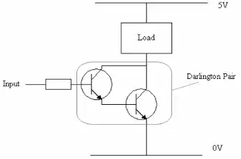
In the above example, it seems more sensible to either (1) place the load below the transistor; (2) use a PNP Darlington; or even better (3) use a complementary PNP pair as shown here:

Example 2

EDIT:

To clarify, one of the questions I'm asking is: Why can't we place this NPN transistor as-is above the load? Or, for that matter, place a PNP Darlington below the load? And also, why do Darlingtons even exist, when a complementary pair looks to be a cleaner solution?

Sod Almighty
  • 1,295
  • 13
  • 22
  • 7
    You seem to think that sharing the current is *a* (or even *the*) function of a darlington, but it is not. The main function is to have a very high current amplification (Beta). – Wouter van Ooijen Jun 09 '15 at 11:52
  • @WoutervanOoijen I merely mentioned sharing the current as an aside. – Sod Almighty Jun 10 '15 at 00:53
  • Even as an aside it is wrong. In normal circumstances the current through Q1 is much lower than through Q2 (by a factor of the Beta of Q2). Hence Q1 can be optimized for high Beta / low current, while Q2 can be optimized for a higher current, which often means a lower Beta. – Wouter van Ooijen Jun 10 '15 at 07:24
  • 1
    If you place the load below the transistor, how do you get enough current into the base of the first transistor? What voltage would you need? – David Schwartz Jun 10 '15 at 10:45
  • @DavidSchwartz I don't know. If I already understood this stuff, I wouldn't need to ask dumb questions like these. Isn't the whole point of a Darlington for situations where the base input is too small? So does the exact base voltage really matter much? – Sod Almighty Jun 11 '15 at 01:01
  • 1
    @SodAlmighty It's for situations where the base current is much smaller than the load current. So anything that makes it even harder to get the base current going is not a good thing. – David Schwartz Jun 11 '15 at 02:38
  • @DavidSchwartz A fair point. – Sod Almighty Jun 12 '15 at 04:15

4 Answers4

9

Sinking load switches with an NPN darlington allow the control signal to be a GND referenced signal. If you use high side sourcing switches it is most typical that then the control signal needs translation down to a GND referenced signal domain.

These days when MCUs are controlling almost everything the GPIO pins on such devices are GND referenced signals. And so it should be obvious why many load switches use the syncing type components with a GND referenced input.

Michael Karas
  • 56,889
  • 3
  • 70
  • 138
  • I agree, this is the primary reason plus NPN BJTs and N ch FETs have better "on resistance". PNP or NPN Darlingtons are "OK" but if the load needs to switch directly to the rails then a MOSFET is substantially more effective. – Andy aka Jun 09 '15 at 11:42
  • Okay, well, without knowing what an MCU is, or being an expert on electronics like you evidently are, I wouldn't call it "obvious" at all. – Sod Almighty Jun 10 '15 at 00:51
  • MCU is a "MicroController Unit", a modified processor chip with funky signal controls (aka GPIO = "General Purpose Input/Output") and other peripheral modules on-chip. You'll find MCUs in toasters these days, let alone everywhere else. Good MCU datasheets usually has some kind of external circuitry reference in them to guide you, so I'd recommend looking up some of those (e.g. www.microchip.com, www.freescale.com) if you're interested in taking this further. – greenbutterfly Jun 10 '15 at 11:39
7

Regarding the use of NPN rather than PNP, Michael Karas answer is correct: you want ground-referenced control signals because the N-type transistors generally have better characteristics than the P-type equivalents.

Regarding other parts of your question: Darlingtons don't share the current between the two transistors 50-50. The one where the input signal arrives on the base carries maybe 1% of the current through it (assuming a beta of 100; most integrated circuit NPNs have betas much higher (~250) so the percentage is therefore even lower). The other transistor is therefore carrying 99%+ of the driven current.

This is a good thing, not a bad thing. Integrated Darlington pairs are configured in physical layout with a significant size differential, such that the main drive transistor has a much larger junction area than the first, allowing for much lower C-E on resistance for lower drive currents and much higher max current handling capability. This is without the need for pairing multiple transistors in parallel, which can cause uneven current splitting due to device differences, even on integrated circuits.

Lastly, NPN Darlingtons can be easily constructed on an integrated circuit effectively as a single meta-transistor; they share the same collector region but have different embedded base/emitter regions (with the size difference I mentioned earlier). Connecting the emitter of the smaller to the base of the larger is pretty trivial. I'm pretty sure this is what's done on the integrated multi-Darlington arrays e.g. ULN2k series (I don't have the details of access any more, but I did see some of this way back when doing my studies in this stuff).

  • That makes sense. I don't see why you couldn't use an NPN Darlington _above_ the load, though... – Sod Almighty Jun 10 '15 at 00:57
  • 1
    @Sod - You can drive a load with the NPN Darlington above the load - but then the control signal needs to swing from near GND up to at least a 1.4 volts above the voltage you want to apply to the load. If you can supply that then all is fine. But in many cases it is easier if the control input is a simpler signal that swings from GND up to the nominal ON voltage of the Darlington without regard to the voltage that the load happens operate at. – Michael Karas Jun 10 '15 at 10:21
  • @MichaelKaras, you also have to be careful of the emitter-collector voltage on the input transistor when sourcing current this way; IIRC pushing the drive transistor's Vce too low can turn off the input transistor by reversing its effective C and E terminals. So, voltage fluctuations on the emitter node could potentially cause the Darlington to switch on and off for at least two different reasons! That's why it's not advisable to use NPNs to source current. – greenbutterfly Jun 10 '15 at 11:30
  • @greenbutterfly I'm afraid I understood none of that. Why would the C-E voltage be any different if you placed it above the load, as from placing it below? And....reversing the terminals? – Sod Almighty Jun 11 '15 at 01:05
  • @MichaelKaras Thank you, your explanation helps clarify the original answer. – Sod Almighty Jun 11 '15 at 01:11
  • Saturation is a wierd non-linear operating mode of BJTs, and does funny tricks to the voltages between the terminals. And BJTs are a forward-biased and reverse-biased diode shoved end-to-end, so you can reverse the C and E terminals... though the physical construction of the transistors means the reverse transistor has much poorer characteristics, so you want to avoid that. – greenbutterfly Jun 11 '15 at 13:20
  • In addition, the current flows the wrong way through the reverse transistor, meaning if that happens the drive transistor is turned off. So, when sourcing current through a saturated NPN Darlington, the input signal's voltage ends up needing to be >1V above the positive supply voltage at the Darlington's collector. Sinking current through an NPN Darlington doesn't suffer this problem, since Vce on the drive transistor is set by the load, not the transistor pair. – greenbutterfly Jun 11 '15 at 13:33
  • @greenbutterfly I understand that it's made of diodes, but I'm really not following you. Why does current flow the wrong way? Why does the base voltage need to be greater than the collector voltage? That should be pretty much impossible anyway. What is "saturated"? Why would the Vce on the "drive transistor" be set "by the transistor pair"? I'm essentially going on GSCE level electronics here, and that about 20 years ago... – Sod Almighty Jun 12 '15 at 04:19
  • Fair enough. FTR, I did this stuff at postgrad level about the same length of time ago, and you learn some really bizarre corner case behaviour when you take it to that level. Regarding saturation, I'm not sure how to distill it down to only a few hundred characters the intricacies of it all. https://en.wikipedia.org/wiki/Bipolar_junction_transistor#Regions_of_operation is a good start. The reasons for the voltage differences is because of there being two transistors not one, so you've got to satisfy the requirements for both. There's no restriction on Vc vs Vb, they're both referenced to Ve. – greenbutterfly Jun 13 '15 at 10:25
5

In the Darlington configuration, the base current of the larger transistor helps to drive the load and is self-regulating. If one needs to drive a 10 amp load and wants to avoid assuming a beta greater than 40, one will need to be able to drive the base of the large transistor with 250mA. To get that 250mA, one would need to drive the base of the small transistor with 7mA. Using a Darlington configuration, if the load draws 10A, 9.75A will flow through the collector of the large transistor and 250mA will flow through the small transistor into the base of the large one. The 7mA driven into the base of the small transistor will be "wasted". If the load were to drop to 10mA, the base of the small transistor would still consume 7mA, which it would pass through the base of the large transistor, but little current would be required elsewhere.

In most other configurations, arranging for the large transistor to have 250mA available on its base when needed would imply that 250mA would be fed to the base of the large transistor even when it wasn't needed. In cases where the load is known to require 10A, that wouldn't be a problem, but in cases where the load might require anything from 10uA to 10A, wasting 250mA at times when the load requires 10mA may be undesirable.

supercat
  • 45,939
  • 2
  • 84
  • 143
  • Interesting, but unrelated to my actual question. – Sod Almighty Jun 10 '15 at 00:58
  • @SodAlmighty: The question was asking, in part, why darlington pairs are used rather than complementary pairs, was it not? The reasons for sinking rather than sourcing current are in general not related to the use of a Darlington except that using an NPN Darlington to source current would have more voltage drop relative to the base voltage than using a single NPN transistor. – supercat Jun 10 '15 at 12:53
  • I don't see why a complimentary pair would waste any more current than a Darlington; given that the input transistor's C-E current, in the absence of load current, would be zero. Also, I don't see why the voltage drop is less relevant below the load than above it. – Sod Almighty Jun 11 '15 at 01:10
  • @SodAlmighty: In most circuits with complementary transistors, the emitter of the transistor that drives the base of the power transistor will be attached to the power rail rather than to the collector of the power transistor. If one tries to use complementary pair with an NPN input and PNP output for high side drive in a fashion similar to an NPN Darlington emitter follower, behavior seems mostly reasonable but as the input reaches the positive rail the portion of current that goes through the input transistor will go up, possibly exceeding its limits. – supercat Jun 15 '15 at 23:46
4

You should be able to see for yourself from your own diagrams that the lower circuit needs access to the power rail, whereas the pure low side switch can be pre-packaged without needing that connection.

Olin Lathrop
  • 310,974
  • 36
  • 428
  • 915
  • Why don't you assume I don't know what I'm talking about, and explain what you mean? Besides, way I see it, the lower circuit needs access to the neutral rail; but the C point goes to the load, not the +V rail. – Sod Almighty Jun 10 '15 at 00:55