See at end for (semi) "full disclosure".
Here is a diagram of a typical Twin T filter from here
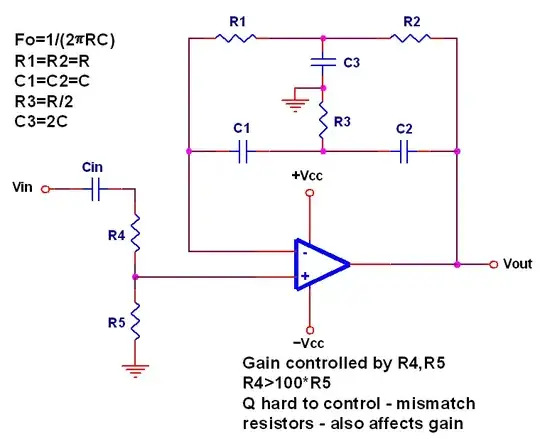
The components names appear to match your example.
Cin, R4, R5 and opamp are additional to your description but are typical of how such a filter may be used.
What's the application?, circuit impedance?, driving circuitry? , required precision?, style of construction ...? (see text).
There is nothing fundamentally wrong with paralleling components BUT, as you note, spurious aspects such as the capacitance of a resistor, may cause undesired effects. The equations assume that all components are "ideal" and eg any capacitance at R3 or R1 / R2 will have some effect on the transfer function. (ESR of capacitors will also notionally be an issue but is liable to be of minimal effect in this application).
Rather than making R3 = two resistors in parallel, you could make R1 and R2 = two resistors in series. This has the effect of halving the effective capacitance (as 2 equal C's in series produce C/2 capacitance). Without plugging the result into the Twin T equations, this is liable to be superior, as the reactance of C/2:2R is 4 times more than C:R/2 (ie the effect of the spurious capacitor relative to the resistance is 4 times less when you place two C's in series across 2R than when you place two C's in pararallel across one R). YMMV in practice :-).
If you wanted to balance the amount of capacitance in each case you could also make R1 and R2 from 2 resistors in parallel - just not equal resistors. While a simple computer program would assist in assigning values to R1a, R1b, R3a, R3b in such cases, a spreadsheet is liable to be good enough for the task and allow quicker investigation.
A rearrangement of the well known formula for resistors in parallel may be useful. ie for Ra, Rb in parallel
- Rparallel = Ra x Rb / (Ra + Rb)
Can be rearranged to
- Ra = Rparallel x Ra / (Rb - Rparallel)
This is obvious but useful.
Use of increasingly precise resistor series will allow increasingly precise accuracies. eg E12, E24, ... . Chances are that 1% values will be ggod enough given other inexactitudes that will be encountered.
Depending on means of construction and resistor case style, capacitances in the order of 3 to 10 pF may prove on the low side for implementation with typical technologies. eg if you are using PCB construction of FR4 of better PCB material and 0805 or smaller SMD resistors and capacitors then stray capacitances may be small enough and controllable. Whereas through hole components on strip board can easily produce stray capacitances of a few pF.
Filter characteristic impedance is affected by relative R to C ratios. If this is a passive filter the loading by driving and driven stages will be of relevance and you may not have much choice in the order of capacitor values. If however the filter forms part of an electronic amplifier or filter as shown in the diagram then you will be able to change R and C value over a decade or few to suit other considerations. eg increasing C value by 2 to 10 times and decreasingly R values by the same amount may be feasible. A factor of 10 change, if achievable, would increase C1 from 3.6 pF to 36 pf, which would be a value far more immune to swamping by stray capacitance. This would (probably) change R1 to 1k. This too would be less prone to shunting by stray capacitance but the ability of your amplifier (opamp, transistor stage or whatever) to drive the increased load would need to be checked. Power consumption may also increase (small in each case) which may or may not be important depending on application.
As well as R & C, the inductance of resistors at MHz frequencies would need to be checked. If through hole resistors were being used then spiral cut bodies may have enough inductance to matter. Small (say 0805 or smaller) SMD resistors would seem unlikely to provide major problems either with absolute capacitance or capacitive balance. Entirely "out of my head" I'd be surprised if an 0805 resistor's capacitance was more than say 0.1 pF, but reputable manufacturers probably provide data.
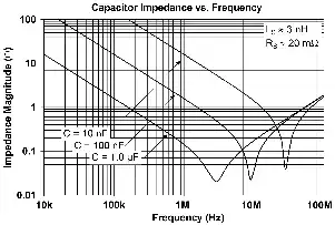
"So your joy may be full" there is also the question of the capacitor's series inductance. Here's an example of impedance plots for 3 values of capacitor, with impedance largely being affected by capacitance and inductance. In this example and probably typically, capacitors in the 10 pF range will not have significant problems with capacitance at around 5 Mhz.
I'd expect balance of say capacitance in resistors to be "good enough". balance.
Precision resistors are going to be easier and cheaper to get than capacitors of equal precision. 1% resistors are commonly available and cheap. Use metal film. 0.1% resistors are available but less common. 1% capacitors are available but getting dearer. Precision tolerance and high stability were typically polystyrene, mica, ptfe. There may be some new wonder dielectric I am aware of.
Ceramics 1% tolerance are available from eg 10 pF at Digikey but thermal characteristics need to be checked.
Digikey offer Mica 1% from 22 pF up
Useful Cornell Dubilier mica capacitor mini catalog here
Thin film 1% from 10 pF up (non in stock)
Disclaimer: I have not 'played' with this order of capacitance in this sort of circuit. I have lots of prior RF experience in this and higher frequency ranges, so a feel for likely capacitances etc, plus lots of experience withfiletrs in general. So comments are based on related experience and acquire common sense. Advice given should make sense based on explanations provided - if it doesn't seem to make sense it may not :-) - but, hopefully it does.