50

I was wondering what the easiest way to figure out a LED's forward voltage is, using measurement tools. I know we can assume red LEDs to be around 1.8V - 2.2V, and that we have similar information for other LED colors, but I was wondering if there's a way to figure out without assuming that.

I purchased several LEDs that don't have a data-sheet with their specifications - so as an exercise I would like to write that information down. (I'm learning)

Most answers I see start by connecting the LED in series to a resistor, but I want to make sure the resistor is right before connecting it.

diegoreymendez
  • 657
  • 1
  • 6
  • 10
  • 1
    This is too vague, and it sounds like you are making everything way too complicated. What do you mean by "right?" If you have a particular current you want to put through the LED, then you can either use a power supply with regulated current output, or build a simple current sink circuit. Hook it up, measure Vf with a VOM. You can measure If, too, if you want. Just make sure the Ammeter voltage drop is not included in the Voltage measurement. After you know Vf at your desired If, you should be able to easily calculate an appropriate resistor value. – user57037 Jun 01 '15 at 21:17
  • 4
    It's also possible my understanding is wrong, so feel free to point out conceptual mistakes in my question. My doubt is: I'd like to figure out the Vf of a LED before connecting it to a resistor. The reason is that I'm a newbie and I'd like to avoid making any assumptions regarding that. Measure first -> calculate -> implement. – diegoreymendez Jun 01 '15 at 21:37
  • 5
    You should always be safe a small current, so you can start with a resistor that you know will be too large, then try smaller and smaller resistors (therefore more and more current). Stop when you are happy with how bright it is. – Austin Jun 01 '15 at 23:05
  • The Wikipedia article [LED circuit](https://en.wikipedia.org/wiki/LED_circuit) has a good explanation about the various calculations and considerations needed for simple LED circuits. – Richard Chambers Nov 16 '17 at 04:56
  • The way I tested them in the past was to pick a resistor based on lowest Vf you would expect, then light it up and measure the actual current. Since you know the Vin, I and R, you can now calculate Vf. R = (Vin - Vf)/I => Vf = Vin - R/I. Or, as was already mentioned, use the diode testing mode of the multimeter. You can also buy (in assembed or DIY kit form) a universal parts tester which can identify and measure important characteristics of various components (search for $20 LCR ESR Transistor checker project). Very useful tool for checking salvaged and/or parts without a datasheet. – Gene Pavlovsky Nov 12 '20 at 10:06

6 Answers6

74

I agree with some of the others here... you're trying too hard.

As others have mentioned, the forward drop of an LED varies with its bias current, but for almost every application a hobbyist will get into, this isn't something you have to spend a great deal of time worrying about.

Almost every handheld multimeter has a diode setting. It will tell you the forward voltage of a diode at the meter's testing bias level (usually a few mA). This will put you in the right ballpark very quickly.

Determining LED Forward Drop (easy way)

  1. Set meter to diode setting (i.e. #14 in this picture).

this picture

  1. Connect the LED to the meter leads, verifying correct polarity
  2. Meter will indicate forward drop (usually 1V-3V for most LEDs.) Note that the LED may glow.

Now that you have the LED's forward voltage drop you can figure out how much voltage everything else in the "chain" will need to drop. For very simple circuits it may just be a limiting resistor. For more complex circuits it may be a bipolar or field-effect transistor, or maybe even something more esoteric. Either way: The voltage through a series circuit will be distributed through all the elements in the circuit. Let's assume a very simple circuit with a red LED, a resistor and the supply.

If the meter indicated 1.2V Vf for the LED, you know your resistor will have to drop 5V - 1.2V or 3.8V. Assuming you want about 10mA through the LED it's now a simple matter of applying Ohm's law. We know that in a series circuit the current through all elements must be identical, so 10mA through the resistor means 10mA through the LED. So:

R = V / I
R = 3.8V / 10mA
R = 380 ohms

If you connect your LED to your 5V supply with a 380 ohm resistor in series, you will find the LED glowing brightly as you intended. Now can your resistor handle the power dissipation? Let's see:

P = V * I
P = 3.8V * 10mA
P = 38mW

38mW is well within the dissipation spec for any 1/4 or 1/8W resistor. Generally speaking, you want to stay well under the power rating for a device unless you know what you're doing. It's important to realize that a resistor that is rated for 1/4W will not necessarily be cool to the touch when dissipating 1/4W!

What if you wanted to drive that same LED with a 24V supply? Ohm's law to the rescue again:

R = V / I
R = (24V - 1.2V) / 10mA
R = 22.8V / 10mA
R = 2280 ohms (let's use 2.4k since it's a standard E24 stock value):

And a power check (using an alternate power equation just to change things up):

P = V^2 / R
P = 22.8V * 22.8V / 2400 ohms
P = 217mW

Now you'll notice that by driving the applied voltage up we have driven the voltage across the resistor up, and that in turn causes the total power dissipated by the resistor to go up considerably. While 217mW is technically under the 250mW a quarter-Watt resistor can handle, it will get HOT. I'd suggest moving to a 1/2W resistor. (My rule of thumb for resistors is to keep their dissipation to under half their rating unless you're actively cooling them or have specific needs laid out in the specification).

JYelton
  • 32,302
  • 33
  • 134
  • 249
akohlsmith
  • 11,162
  • 1
  • 35
  • 62
  • Sublime answer, except that C-E drop at saturation in a transistor doesn't need to be (and often ins't) 1.4V, otherwise everything perfectly explained and worked out. – Asmyldof Jun 01 '15 at 22:02
  • Yep, hence the "very roughly" :-) Thank you for the feedback, I'll make some edits to clear things up – akohlsmith Jun 01 '15 at 22:04
  • I wanted to send you a message, but I can't seem to find a way, nor to start a chat, so I'll just do it here anyway (I've been away too long before a week ago). See figure 4: https://www.fairchildsemi.com/datasheets/BC/BC547.pdf at 20mA it's only ~0.06. And that's a crappy BC500 series. So, that is only _very_ roughly 1.4. ;-) – Asmyldof Jun 01 '15 at 22:09
  • Thank you for the detailed reply. A few extra doubts I have: 1. My multi-meter has symbols 11 and 14 at the same position (diode on top of speaker-like symbol). Can I safely assume that's the correct diode position? 2. I have a feeling that since people tell me I'm trying too hard something I'm doing is inherently wrong - shouldn't I try to figure out the Vf first? Thanks! – diegoreymendez Jun 01 '15 at 22:11
  • @Asmyldof I've edited my answer to eliminate the potentially misleading Vce spec. You're absolutely right, it depends a LOT on other factors. – akohlsmith Jun 01 '15 at 22:17
  • 2
    @diegoreymendez Yes, my meter has them both on the same setting as well. Usually there will be another button to select between modes on the same selection switch position. Consult your meter manual for the details for your meter. – akohlsmith Jun 01 '15 at 22:18
  • @akohlsmith - I'll use transistors but not just yet. I'll open up a new question for that. – diegoreymendez Jun 01 '15 at 22:18
  • 3
    @diegoreymendez you're right, you do want to know what the Vf is in order to drive it correctly but what we're all saying here is that a very rough "rule of thumb" is appropriate for this kind of application. A lot of newbies get caught up in being very precise when there is no need for more than a bit of precision. When you must be precise and when you can be general comes with experience and usually with destroyed parts as well. :-) – akohlsmith Jun 01 '15 at 22:19
  • My multi-meter is returning 1690 for red LEDs. I assume this is 1.69V? The weird part is it's returning a perfect "1" for green, blue and yellow LEDs even though they light up. – diegoreymendez Jun 01 '15 at 23:03
  • 4
    @diegoreymendez: Your meter apparently has a maximum reading of 1.99 volts in the diode test mode, so it can't indicate the Vf if it is higher than that. You'll have to use one of the methods mentioned in other answers for the higher-voltage LEDs. – Peter Bennett Jun 01 '15 at 23:28
  • Maybe it's not part of the original question, but how do I figure out the LEDs rated current? You assumed 10mA, but this may be suboptimal. Is there a way to assess the perfect current, too, without a data sheet? – Ned64 Jun 02 '15 at 13:07
  • 1
    @Ned64 without a datasheet you're reduced to experimenting. A light meter and variable resistor will give you a curve showing input current vs light output. It'll be a little more complex than this, but really there is no such thing as "perfect current" - all components will vary with PVT. Pick a value that works for the 80% case (which is really probably 99%) and run with it. – akohlsmith Jun 02 '15 at 19:45
  • @akohlsmith Many thanks - too bad it's not so easy. I have an LED panel without driver and just don't know which constant current driver to buy. – Ned64 Jun 04 '15 at 09:00
  • @Ned64 Is it important to have a constant current driver? Is the supply voltage wildly varying (several volts) or is it absolutely required that the LED have a specific brightness that is unvarying? If not, guess at 20mA, calculate the resistor and slap it in. Tweak as needed. – akohlsmith Jun 04 '15 at 13:18
  • @akohlsmith It's a 600mmx600mm panel of 576pcs 3014 SMD LED in some unknown configuration. I thought the standard way to power it would be a constant current driver, like the one I use for my COB lights. I tried a 300mA driver, which resulted in 34V voltage drop. The panel clearly needs more, but I don't know how to find out without damaging the panel (e.g. by pairing it with a driver of too high voltage/current). – Ned64 Jun 04 '15 at 14:15
  • @Ned64 ahh see that's quite a bit different. :-) and yes, something like that would be a very good candidate for a constant current driver. You might want to take a look at backlight drivers for LCDs and whatnot; they usually have long strings of white leds and have constant current drivers which can go up to higher voltages. – akohlsmith Jun 04 '15 at 14:17
  • @akohlsmith (sorry, not allowed to chat, not enough points) Maybe I can try varying the current in a friend's lab (with his power supply), but where to stop? Is there perhaps a voltage limit over a single (white) LED that I could watch out for? – Ned64 Jun 04 '15 at 14:28
  • @Ned64 I think it would be worth posting a new question with your specific scenario. Include pics of the panel and tell us what you've tried and ask how to go about driving this thing. Include a link to this question since it's related but not quite the same. – akohlsmith Jun 04 '15 at 19:45
  • @akohlsmith Thanks again, I have: http://electronics.stackexchange.com/questions/173968/how-do-i-find-out-which-current-voltage-to-use-for-an-unlabelled-led-panel – Ned64 Jun 04 '15 at 20:08
17

If you have a power supply with adjustable current limit (like this one), then it becomes very easy.

  1. Set the output voltage to around 5V and dial the current limit all the way down.
  2. Connect the diode directly to the power supply, with no resistor. Don't worry! You've already limited the current!
  3. Dial up the current until it reaches your target (say, 20mA).

The power supply is limiting the current through the LED to the dialed-in limit. The voltage display will show you what voltage is required to push that much current. That's your forward voltage!

bitsmack
  • 16,747
  • 9
  • 52
  • 108
  • that doesn't seem fast or easy, but it will work. For me, fast and easy is using my meter's diode drop setting and measuring the LED. :-) – akohlsmith Jun 01 '15 at 21:32
  • @akohlsmith That's true! You should put that in an answer! I find that my meter only gives a rough estimate, since the Vf can be considerably different at 1-2mA than at 20mA... – bitsmack Jun 01 '15 at 21:34
  • 2
    There's no need to short the output, just crank the current limit down to zero, connect the LED across the supply, then adjust the current for the desired LED current and read the supply's output voltage. That'll be Vf. – EM Fields Jun 01 '15 at 23:10
  • @EMFields Hah, I've been doing that extra step for years! My thanks to you. I'll edit the answer... – bitsmack Jun 01 '15 at 23:15
  • When you say "desired LED current" it seems to me like I should first decide on the current I'll use and then figure out the voltage. Is that correct? Does that value come from specs too? - right now I have no specs for my LEDs – diegoreymendez Jun 01 '15 at 23:18
  • 1
    @diegoreymendez Yes, the reason for the series resistor is to limit the current flowing through the LED. Your "standard" LED, called "5mm" or "T 1-3/4", can generally handle 20mA. Some surface-mount LEDs can only handle a few mA, wheareas a 3W LED can handle a full amp (at Vf = 3V!). The more current, the brighter the illumination. I usually find that 5mA is sufficient for a 5mm LED, even though it can take 20mA. It depends on your application. – bitsmack Jun 01 '15 at 23:24
10

Most common LEDs can handle at least 20 mA, so if you select a resistor value that will pass 20 mA when connected directly across your power supply, a LED will not be damaged when connected in series with that resistor. Then just measure the voltage across the LED to get the LED's forward voltage. The LED voltage will vary slightly with current, but the current you eventually choose to use is not at all critical.

I generally assume that common red, yellow and green LEDs are about 2 volts, and I aim for about 10 mA current (although I recently had some extremely efficient green LEDs where I had to reduce the current to under 1 mA to get the desired brightness (dimness?)). No real need to get extremely scientific about it!

Peter Bennett
  • 57,014
  • 1
  • 48
  • 127
  • 2
    I, in fact, recently sampled a couple of reels from a Chinese fab and the deep red, emerald green, aqua and orange LED were so bright, in normal test-boards to indicate logic signals I use 0.05mA to avoid blindness in the case of a full byte 1's at once. – Asmyldof Jun 01 '15 at 21:32
10

To expand on Peter Bennett's answer: take your LED, add a 1k resistor, and apply 12 volts (making sure to get the polarity right). Now measure the voltage across the LED. This will give you Vf at about 10 mA. If you want to know Vf at 20 mA, us a 500 ohm resistor. If you want to know Vf at 1 mA, use a 10k. None of these numbers is super precise, but knowing Vf precisely is not a generally useful idea. At the very least, Vf will vary with temperature, so obsessing about it won't get you anywhere.

WhatRoughBeast
  • 59,978
  • 2
  • 37
  • 97
4

You misunderstand how an LED works in that Vf isn't the voltage you put across an LED to make it work, it's the voltage that appears (is dropped) across an LED when current is forced through it.

If you look at a proper data sheet you'll see Vf(min), Vf, and Vf(max) specified for a particular current, and what that means is that if you force the specified current through the LED, you can expect Vf to fall anywhere between Vf(min) and Vf(max), With Vf being the typical value.

So, the answer to your question is:

enter image description here

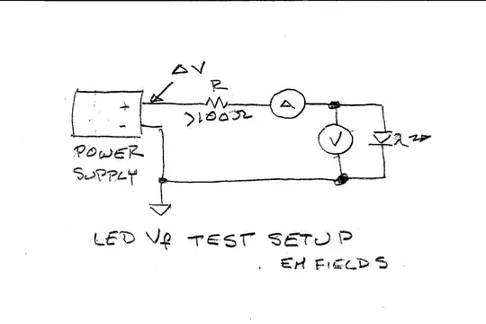
The power supply is any voltage-variable supply, R provides a ballast for the LED, decreasing its sensitivity to power supply variations.

That'll keep the LED from releasing its magic smoke if you inadvertently crank up the supply too far, and its value [R] isn't critical, within reason.

For example, if you use a 1000 ohm resistor and you're trying to push 20 mA through the LED, that 20 mA also has to go through R, so R will drop:

$$ \text{ E = IR} = 0.02A \times 1000 \Omega = \text {20 volts,} $$

and you'll need some headroom on top of that for the LED.

"A" is an ammeter used to measure the current through the LED, and "V" is a voltmeter used to measure the voltage across the LED.

In use, what you'd do would be to start the supply off at zero volts and then crank it up until the ammeter read 20 milliamps, then the voltage displayed on the voltmeter would be Vf for that particular diode at that particular current and ambient temperature.

Referring back to your question, the way to determine what value of series resistance is "right" for your LED is first to determine its Vf at the desired forward current (If) and then to use Ohm's law to determine the value of the resistance, like this:

$$ \text {R = } \frac{Vs - Vf}{If} $$

Assuming, then, that Vs (the supply voltage) is 12 volts, that Vf is 2 volts, and that If is 20 mA, we'll have

$$ \text {R = } \frac{12V - 2V}{0.02A} = \text{500 ohms} $$

Then, to determine the power the resistor will dissipate we can write:

$$ \text{Pd = (Vs - Vf)} \times \text{If}\ = \ \text{10V} \times \text{0.02A} = \text{0.2 watts} $$

510 ohms is the closest E24 (+/-5%) value that'll keep If on the conservative side of 20mA, and a 1/4 watt resistor should be fine.

Duck soup, eh? ;)

EM Fields
  • 17,377
  • 2
  • 19
  • 23
  • 1
    It does go both ways though. If you had a perfect voltage source with V = the LED's Vf at some current, and nothing else, the LED would pass that current. Of course, the bad news is if you're a little over (imperfect supply, drift due to temperature, etc.) your current might be significantly higher and blow out the LED, so it's not a good way to regulate things in practice. – hobbs Jun 02 '15 at 04:19
2

Build a constant current source because common bench supplies wont go down that low.This could be an easy 1 or two transistor circuit . It is easy because it doesn't need to be accurate . A sensible current would be the current that you intend to drive the led with . Now your DVM will give you the forward volts measurement and you wont blow any LEDS

Autistic
  • 14,235
  • 2
  • 27
  • 65