6

Seemingly illogical pinout has been discussed before, but my question is different.
Have a look at the pinouts for the Si8540:

Si8540 pinouts

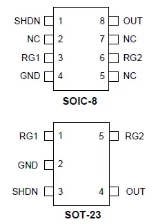
One would think that the pin order would be the same for both packages, maybe rotated, but that would be it. Instead the SOT-23 pinout is almost a mirror image of the SO-8's. Now SO-8 nor SOT-23 are flip-chip, so the die isn't mounted upside down on either, and I can't imagine that they would make a different die for the other package. I can only presume they crossed the bonding wires.

Looks like asking for trouble IMO, so why is this done? I can't think of another explanation.

Federico Russo
  • 9,658
  • 17
  • 68
  • 117
  • 1
    Could be desired compatibility with a competing chip.. I used be in Semi and we have done this all the time. The idea was to offer a pin drop out and under cut them to get the biz. – Frank Jul 24 '11 at 10:21
  • @Frank: could be. Isn't crossing the bonding wires not a problem? – Federico Russo Jul 24 '11 at 11:39
  • @Frederico not really.. Depends on the signals, speeds etc. Those wirebonds are incredibly sturdy.. Weird but true.. – Frank Jul 24 '11 at 14:32
  • possible duplicate of [Difference between TL431 and TL432](http://electronics.stackexchange.com/questions/5345/difference-between-tl431-and-tl432) – endolith Jul 24 '11 at 16:50
  • @endolith I don't see how that is an exact duplicate at all. – Kellenjb Jul 25 '11 at 12:22
  • @Kellenjb it's also a question about why a single part has two different pinouts, with answers explaining why the manufacturer would do that. the only difference between the two questions is the example part number. – endolith Jul 25 '11 at 13:01
  • @endolith The other question is about why a manufacture would have 2 pin-outs for the *same* package. This is about why the manufacture would drastically change the pin-out order for *different* packages. – Kellenjb Jul 25 '11 at 13:05

2 Answers2

3

Per Stevenh's recommendation, I am placing my comment as an answer and extending it.

Could be desired compatibility with a competing chip.. I used be in Semi and we have done this all the time. The idea was to offer a pin drop out and under cut them to get the biz. Wirebond is a sturdy piece of technology and last I checked people are moving to copper from gold. Most of the chips are tested at 50g drop tests, I don't remember us failing them at all.(BTW, these tests are never ever mentioned or released unless you are a serious customer due to hassle of answering questions)

In terms of signaling crossing wires is generally a no no, however don't assume there is a single pad for that pin. Depending on the marketing input, I remember we made several bond out options where we use different pads for the same functionality.

Frank
  • 2,812
  • 5
  • 30
  • 37
  • In college (granted, more than just a few weeks ago) we learned that for die bonding typically aluminium (alloy) is used, except for high current connections. – stevenvh Jul 25 '11 at 06:55
  • 2
    Well.. I just transferred 20-30 parts from Gold to Copper about 8 months ago.. Spend a ton of time qualifying them.. These were for a very very large mobile customer.. So probably my information beats yours. :) – Frank Jul 25 '11 at 07:39
  • Yes, apparently. Still puzzles me why you would choose the obviously more expensive gold over the cheaper aluminium. Lower specific resistance doesn't help if you make your wires thinner. – stevenvh Jul 25 '11 at 07:47
  • @stevenvh Why gold over copper, I really don't know. But we had to qualify and this usually means tests like HTOL (baking the chips to see how may hours before they fail), drop tests etc. I suspect, gold is probably a better in one or more of these. I doubt it is just conductivity. – Frank Jul 25 '11 at 08:16
2

I don't think the package pin outs are as different as you think they may be. You can remove the NC from the picture all together since they don't really make any difference. Now If you flip it vertically you will see that the pin outs are almost identical.

     _________
GND |         |
RG1 |         | RG2
    |         |
SHDN|_________| OUT

The only difference is that the GND and RG1 are switched, which is a minimal difference and could be planned for on the die itself.

Pin compatibility with competitors can be a huge deal. If a company is in their production stage and has something fall through with one IC, it can be really easy to just switch to a competitors IC assuming the pin outs are the same.

Kellenjb
  • 17,509
  • 5
  • 51
  • 87
  • Obvious as it may look, flipping vertically would be a big deal!! Using the same bonding pads it would mean the die has to placed **upside down**, as Federico noted. IMO it's **absolutely impossible** that they do this for a SOT-23 or SO-8. – stevenvh Jul 24 '11 at 13:24
  • @Stevenvh Or they flipped the design vertically for the die. There is extra cost associated with having 2 different dies to fab, but the engineering cost would be essentially 0 since it would act exactly the same. – Kellenjb Jul 24 '11 at 13:36
  • @steven, IANA-VLSI-engineer, but I don't quite get why flipping a die vertically is "impossible". The packages for some SOTs are virtually symmetric along the mould line, so all it would take to invert the pinout would be to flip the entire package before the leads are formed. – Nick T Jul 24 '11 at 17:01
  • @Nick - I agree that it's not so impossible after all :-). But likely? I don't think so. They would have to change their tooling and create a new package (it's not completely symmetrical). And in the end they *still* have to cross bonding wires, so what did they gain after all? – stevenvh Jul 24 '11 at 17:09