1

I've built a run of simple boards like the one shown below to control LEDs in automobiles. The boards have twenty of the NX3008 mosfets in an open-drain configuration as shown, which are controlled by a PIC24 with PWM. I kept the circuit simple in order to keep the chip count down and therefore the cost low, but I am finding that a number of my customers are damaging the mosfets either by shorting them to +12 momentarily, overloading them, or (maybe) damaging them with ESD. I myself have not handled them very carefully at all and have yet to damage one with ESD, however, this is happening often enough that I'm skeptical that the other two causes of failure are the only ones. Other than that, the devices have been very reliable once installed correctly on the vehicle.

Anyway, I'm looking for suggestions on how to prevent or mitigate damage to these mosfets.

I considered adding a ~5-ohm source resistor, however, this would not only almost double my chip count but would potentially dissipate a lot of heat on this little board when all 20 going at once. Is there maybe a better part to use?

schematic

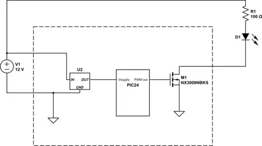
simulate this circuit – Schematic created using CircuitLab

  • 1
    Have you received a sample from the field or is this just what they say ? – efox29 May 29 '15 at 03:36
  • Those are pretty wimpy MOSFETs (30V/230mA) for the automotive environment. What is the failure mode? Any chance the the power connections were mixed up too? Unfortunately, making things idiot-proof tends to be non-trivial. – Spehro Pefhany May 29 '15 at 03:43
  • Perhaps weak, yes. They are only supposed to power a few LEDs each though. With 20 in total, you should get over 4 Amps. – Kyle Gregory May 29 '15 at 04:33
  • Component count vs. customer situation. Tough call. – copper.hat May 29 '15 at 04:35
  • Fortunately, it's got more outputs than most people need so when a customer fries one, I just have him reprogram it to use a different output instead. Nobody's really freaking out about this, but its obvious that the product is not quite ready for prime-time. Then again, there's not much of a market for it anyways. – Kyle Gregory May 29 '15 at 04:39
  • @efox a few customers have sent in videos and it's usually pretty obvious what happened. Most of my customers are repeat business who are making money by installing these for people either professionally or as a hobby. Many of them openly admit guilt and are happy that the card is still usable for them. In fact, I haven't had a single customer demand his/her money back or even a replacement, so that's been a blessing. – Kyle Gregory May 29 '15 at 04:55
  • Who installs the 100 ohm resistor? – Andy aka May 29 '15 at 08:34
  • The customer installs the resistor because it's dependant on which LED and how many they use. All of our customers understand this. – Kyle Gregory May 29 '15 at 12:51

2 Answers2

2

One fundamental problem is that you're probably (you haven't said what your LED current is) not operating the MOSFET within its Safe Operating Area. Never go by the 'headline specs' on page-1 of a datasheet. Check page-4 Fig.3 of the datasheet, for DC operation (curve-3 or 5), at say 15V (i.e. car battery is charging), this MOSFET doesn't want to be carrying more than about 50-60mA. With 100ohm in series with your LED, knowing nothing about the LED, my suspicion is that you're at or over that limit, in which case MOSFET death is just a matter of time.

But you may be right, it may be user installation SNAFUs that's causing MOSFET failure. At the very least I'd add a 'polyfuse' (a PTC self-resettable fuse) between the LED & the MOSFET, to provide some over-current protection. Places like Littlefuse & Belfuse have plenty of guidance on selecting the right thing here.

I'll assume you're using a +5V PIC24 on a %V Vcc, and not a 3.3V one, as that MOSFET won't be saturated on with a 3.3V PIC's GPIO. I have a disturbing feeling that if you're quibbling about a single protection resistor that you may not even have decoupling caps on the MCU's Vcc-to-Gnd pins nor on the input & output of the Vregulator. This is bad at the best of times, but especially in the hostile environment of a car.

Selling a product that customers have to install themselves, without "protection" of various kinds, is a recipe for disaster. Customers always reverse the polarity when connecting things like this, or as you guessed, put 12V into the MOSFET's D, and other atrocities that are an unavoidable challenge to try to mitigate. This is one of the differences between a hobby-project and a product :)

Techydude
  • 4,089
  • 15
  • 23
  • These mosfets are actually specced for 350mA in the regular part of the datasheet. Most of the time, they are operated at less than 100mA but a few customers haven't read my datasheet and have exceeded that. Nonetheless, it would be nice if it had some protection so that it would simply turn off instead of blowing up. – Kyle Gregory May 29 '15 at 04:31
  • No, its a 3.3V PIC, I didn't notice the saturation voltage. I do have decoupling caps and a voltage regulator. All the parts are spec'd for automotive applications except the mosfets. – Kyle Gregory May 29 '15 at 04:35
  • Then you've just confirmed my suspicion - "Up to 100mA" with a 14.somethingV battery being recharged, even at an ideal 25C (i.e. room temperature), you're beyond the SOA envelope. I'd majorly beef up the MOSFET, and add a polyfuse with, say, 100mA hold-off current, to protect against predictable customer stupidity. – Techydude May 29 '15 at 04:39
  • even at 3.3V Vgs, the Rds should be pretty close to what it is at 5V Vgs though, right? Or am I missing something? I'm looking at figure 9 here: http://www.nxp.com/documents/data_sheet/NX3008NBKS.pdf – Kyle Gregory May 29 '15 at 04:42
  • 1
    When it comes to binary on/off applications, don't screw around in the un/marginally-saturated region, otherwise you're just creating problems where they don't need to be; you'll want a 'logic-level gate voltage' MOSFET. – Techydude May 29 '15 at 04:45
  • I'm pretty sure it is a logic level gate input - at least according to digikey. That was part of my selection criteria. http://www.digikey.com/product-detail/en/NX3008NBKS,115/568-10407-1-ND/4333336 – Kyle Gregory May 29 '15 at 04:52
  • " DC operation (curve-3 or 5), at say 15V (i.e. car battery is charging), this MOSFET doesn't want to be carrying more than about 50-60mA. With 100ohm in series with your LED, knowing nothing about the LED, my suspicion is that you're at or over that limit, in which case MOSFET death is just a matter of time." - If MOSFET is on, Vds is not 15V, it is way less. With Vgs = 3.3v, the Rds is like 2 Ohm, which is, combined with Rled=100 Ohm gives us millivolts. – ilkhd May 29 '15 at 08:36
  • I'm not sure what is your point @ilkhd? – Kyle Gregory May 29 '15 at 12:58
  • @ikhd correctly corrected my error :), you probably are operating within the SOA. so if your customers really are reporting 'dead on arrival' (i.e. dead upon first use after they've frakked it by incorrect connections) then i'd definitely be considering (a) polyfuse protection, & (b) reverse-polarity protection, at a minimum. there's several dangers in vehicle 12V systems, and I'd urge you to review the advice in the link posted in the other answer too. – Techydude May 29 '15 at 13:37
1

Your regulator circuit seems painfully simple, if you are using an LDO as the symbol implies I would think it gets pretty warm due to the voltage differential between 12v (usually 14v or more) and 3.3v. I would switch to a buck regulator if you aren't already using one.

Do you have any suppression circuitry to handle load dumps and other hazards? Load dumps can result in momentary spikes up to 90v.

I know you said you personally had not experienced any ESD issues, but I would add ESD protection to the GPIO outputs of the microcontroller. The VESD05A8A-HNH will protect 8 outputs so you will need three of them. Very small, 1.4mm x 1.65 mm. 40 cents in quantities of 100 from Digi-Key.

tcrosley
  • 47,708
  • 5
  • 97
  • 161
  • The current draw is only about 12mA so the regulator heat is not bad at all. The inputs have a level shifter circuit that accepts 12V logic from the vehicle, that circuit provides ESD protection for the PIC. I want to focus this discussion on the MOSFET, which is where all of the problems have been. – Kyle Gregory May 29 '15 at 13:09
  • @KyleGregory Gotcha. I was just making sure you had the power supply end taken care of, due to the "block diagram" nature of the schematic I couldn't tell. A lot of people don't understand the issues with an automobile's 12v rail, which is usually way above 12v and subject to huge spikes and a lot of noise. – tcrosley May 29 '15 at 13:13
  • I appreciate it. I kept the schematic simple because I didn't want to draw the whole thing but I wanted to show what was going on overall. – Kyle Gregory May 29 '15 at 13:15