15

Old Valve Amp

Image from: here.

This image is the schematic of an old Tesla 521A valve amplifier radio. On the following resistors in the schematic there are weird markings: R4, R5, R6, R24, R25, R26

I am guessing they signify the wattage of the individual resistors. As I have this specific circuit heavily damaged and I would like to salvage the parts, it would be great to know what wattage do these signify(or what else they mean)

I know that these symbols are definitely not standard, but I guess maybe someone here has met these.

If the symbols are not good enough I can supply images of the resistors too.

akaltar
  • 587
  • 8
  • 20

3 Answers3

24

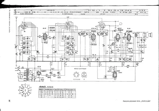
You're nor right about standard because, in fact, this was a standard! Widely used up to around 1960's, especially in Europe. You can find that resistor symbols on almost every schematic of vacuum-tube-based device made in Europe in these past days.

Line(s) inside a resistor indicates its wattage in following manner (typically, but not always):

Three slanted lines [ /// ] - 0,05W

Two slanted lines [ // ] - 0,125W

One slanted line [ / ] - 0,25W

One "parallel" line [ - ] - 0,5W

One "perpendicular" line [ | ] - 1W

Two lines [ || ] - 2W

Letter V [ V ] - 5W

Letter X [ X ] - 10W

The most "recent" standard which recalls that symbols is (in my country Poland) PN-89/E-01215 - it is based on international standard IEC 617-4/1983. But in IEC standard there is only a general symbol of resistor - rectangle. Resistor symbols with lines inside are widely used in books about electronics from "cold war era" and of course in manufacturers schematics. Sometimes You can find a legend somewhere in the schematic which explains non-standard or non-typical symbols. And sometimes it would make a little bit of confusion - I've seen a schematic where resistors have left-slanted and right-slanted lines to indicate different wattages, where one slanted line indicates 0,125W, where roman digits indicates non-typical wattage [ VI ] for 6W resistor, etc.

If there is no lines inside resistor rectangle and any legend assume 0,25W - this is the most used wattage.

Jakub Rakus
  • 2,225
  • 5
  • 18
  • 26
1

I've worked a lot with valve circuits but I haven't seen these exact symbols. I'll ask someone who might know for sure, but just by looking at R24 and R25 I'm quite positive those would have to be several watt resistors. R24 connects directly to the rectifier tube and thus is drawing all of the current for the circuit across itself. The lines may be an indicator of how many watts. I.E. R24, R25, and R4 may be 2 watts, and R5 may be 1 watt.

I'll place an edit if I can get an answer for sure.

Korozjin
  • 513
  • 3
  • 10
-2

I've often seen R followed by a number meaning WHICH resistor, and saying nothing about the wattage or the resistance.

One result of this is that you'll see no two resistors in the same circuit marked as R followed by the same number.

user6030
  • 93
  • 4
  • "_**On the following resistors in the schematic** there are weird markings: R4, R5, R6, R24, R25, R26._" You've missed the whole point of his question. R4, 5, 6, etc. are the resistors with the strange symbols. – Transistor May 23 '16 at 22:11
  • "On the following resistors in the SCHEMATIC there are weird markings". The SCHEMATIC usually has the R(number) markings to give each resistor a separate name. The physical resistors seldom do. The physical resistors are more likely to have markings which show their resistance, with the wattage shown only by the size of the resistor. – user6030 May 28 '16 at 01:27
  • Zoom in on the schematic and have a look at R24 (bottom left). You will see two lines _inside_ the resistor symbol. R5 (bottom centre) has one line and R6 has one line on-axis. That's what the question is about. – Transistor May 28 '16 at 08:06