0

I saw this question and I think I have a similar problem/question.

I have:

  1. IP Camera, DCS-7010L, 5 V, 1.2 A

  2. PIR, HC-SR501 (like the one of Kudos@Dave ... I think), 4.8-20 V(dc) input, 3.3 V output

I connect the PIR to the alarm (DI/DO) of the camera, without any transistor or similar, and it is OK.

But, the question is: can I connect 2 or more PIRs to the DI/DO of the camera in parallel as shown?

proposed connection diagram with two PIRs in parallel

  • 1
    I am surprised this was closed, as it relates to design. – Bort Jun 19 '18 at 12:01
  • @Bort Connecting ready-made modules to a ready-made camera is hardly *design*. How is this different from e.g. "Can I connect my USB2.0 mouse to a USB3.0 laptop?" kind of question? (except that a question about standard interfaces like USB can actually be answered without guessing) – Dmitry Grigoryev Oct 26 '18 at 10:45
  • @DmitryGrigoryev - Your USB example is a question about forward compatibility with a particular standard...Which I dare say is still related to design. There are many power/data protocols/buses with variations that may or may not work together, and a designer may wish to know which protocol to use for their project. Regardless, this PIR question asks if two logic signals can be combined in parallel. The answer involves adding three additional components. The question may seem awfully simple to you, and may even have been asked here before, but don't forget that you were once a novice as well. – Bort Oct 26 '18 at 11:23
  • @DmitryGrigoryev - Also consider that questions about component identification, methods of soldering, and "*My multimeter probes are too big to measure a laptop battery*" are apparently on-topic here. How is a question about (multimeter probe size) any what more about design than OP's PIR logic signal question? – Bort Oct 26 '18 at 11:23
  • @Bort It's not about how simple/complex the matter is. If the question included the schematic of the PIR sensor, we could tell how to combine the signals properly. If a device is a black box, the only way to correctly answer the question is to read the manual, at which point it's a usage question. The current answer makes a guess that combining PIR signals may require diode OR circuit, but there's no evidence that it's actually needed. An answer suggesting to connect them directly could just as valid. Don't you see a problem with a question to which two contradicting answers are both valid? – Dmitry Grigoryev Oct 26 '18 at 13:01
  • @DmitryGrigoryev - I agree that ideally this question would have a schematic provided. However, the model number was given, and schematics are available. Even without that, it is conceptually about logic levels being combined in parallel. I don't see a "problem" where two "contradicting" answers are both valid. If an answer to a question is "*You need either a pull-up or pull-down*", I don't find that to be a huge issue, just not ideal. The majority of content there is that a signal needs to be pulled. The direction is secondary in priority. – Bort Oct 26 '18 at 13:22
  • @DmitryGrigoryev - I don't find this to be a true "black box", because PIR modules are very common, and again there was a model number provided. I can actually update the question to provide the schematic when I get home. If the schematic is included in the question, would that satisfy your interpretation of a design question? If not, what else is needed? Keep in mind that my surprise of this being closed was in relation to the many things here I find to be *less* about design. – Bort Oct 26 '18 at 13:24
  • @Bort I'm not in any way opposing your effort to save the question. I'm just defending the position that it was rightfully closed in its current state. – Dmitry Grigoryev Oct 26 '18 at 13:28

1 Answers1

1

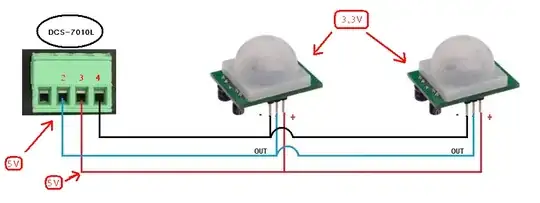
You cannot simply put the PIR modules in parallel to your camera's input. The PIR modules provide a logic level signal, and putting them in parallel would cause the modules to short circuit each other's output.

In the simplest case, you could use a diode OR circuit to allow the PIR modules to drive the camera input either high or low. Unfortunately, I am having some trouble downloading the camera handbooks so I don't know whether you need to drive the input high or low.

Depending on what the camera needs:

If a low signal means start the camera, use diode OR with the cathodes towards the PIR modules and a pull up resistor on the camera input.

High signal means start the camera, use diode OR with the cathodes towards the camera, with a pull down resistor on the camera input.

Diode OR on Wikipdia.

JRE
  • 67,678
  • 8
  • 104
  • 179