I need to drive a DC motor @ 24V, 6A with a MOSFET. How can I sense the current that the motor is drawing with a microcontroller? I have to know when the motor is stalled.
Asked
Active
Viewed 1.2k times
4 Answers
17
You place a small sense resistor (typically < 100m\$\Omega\$ for the voltage and current involved) in series with the motor and measure the voltage drop. There are two methods: high-side and low-side, depending on the position of the sense resistor.
Low side is easiest, as the voltage drop you want to measure is directly related to ground, but it lifts the low side of the motor's voltage a few tens of millivolts above ground too, and not everybody likes that. If it's no more than these few tens of mV it shouldn't be a problem though, and you can use an opamp to amplify the voltage in a simple non-inverting amplifier configuration. A 10m\$\Omega\$ resistance will give you a 60mV drop, which is acceptable, and at the same time high enough to measure properly. You don't necessarily need a physical component for this; a 1cm PCB trace 0.5mm wide has a 10m\$\Omega\$ resistance.
Make sure to select an RRIO (Rail-to-Rail I/O) opamp.
For high-side measurement you have to use a difference amplifier to measure the voltage drop. There are special ICs for that, some of which have the shunt resistor integrated, for maximum accuracy.
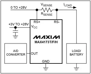
But you can also construct your own difference amplifier with an opamp. If you just want to detect a stall you probably don't need the A/D converter but can use a simple comparator. Be sure to filter the measured voltage with a capacitor.
A (not very thorough) search turned up the SiLabs Si8540 high-side sensor, available from Mouser from USD 0.65 quantity one.
edit
The Zetex/Diodes ZXCT1009 is comparable, but only needs 3 pins of its SOT23 package.
Further reading:
Linear Technology Current Sense Circuit Collection (warning: heavy product plugging!)
Collection of documents on current-sense amplifiers by Maxim
stevenvh
- 145,145
- 21
- 455
- 667
-
1I am very happy to see that you often take the time to show an example part that will get the job done but your lesson that comes first teaches more then enough to allow you to bypass the shopping advice. – Kortuk Jul 22 '11 at 19:01
-
@Kortuk - Got it. Removed shopping advice. (but left reference to example part) – stevenvh Jul 23 '11 at 07:20
-
It was a "good job" message. I thought the link was a nice touch. You give some basic, here is a part that would work, but by the point you read this you will have learned how to select your own. People always assume a mod is unhappy! – Kortuk Jul 23 '11 at 12:15
-
@Kortuk - well you can't blame them! ;-) – stevenvh Jul 23 '11 at 12:17
6
People who think the only way to measure DC current is to use a shunt resistor may be surprised to learn that a variety of current sense techniques exist.
Hall effect sensors are nice for measuring large high-side DC currents. Some have analog out, eating up one of the analog inputs on your microcontroller. Others have an integrated internal ADC, with digital pins that directly connect to your microcontroller. A few also have an integrated power FET driver, and are smart enough to unconditionally turn off the FET when it measures over-current.
In many cases, I don't really need to know exactly what the current is, I just want to keep things from getting permanently damaged when the motor stalls out. It makes the rest of the system much simpler to use a "smart switch" that automatically turns itself off when the motor stalls.
The Allegro Hall effect sensor chips look nice. The IR intelligent power switches look nice.
Related: Best shunt resistor for power meter application? and High-bandwidth current measurement
-
Honestly I was curious, but that "variety of techniques" appears to be for 80% shunt resistor based: high side, low side, voltage drop over MOSFET, ... – stevenvh Jul 24 '11 at 18:47
-
@stevenh - he did say "large" in addition to high side at the start of that paragraph. It's easy to imagine how a shunt could get unpleasant in such circumstances. But in more common situations it tends to work pretty well. – Chris Stratton Jul 28 '11 at 08:04
-
1Another reason to go with the hall effect sensors are that they are isolated and can have very microcontroller friendly outputs. – W5VO May 31 '12 at 12:16
3
As current, voltage, and resistance are all related (Ohms law), you can measure current by measuring the voltage drop across a known resistance and calculating it:
\$I=\frac{V}{R}\$
Put a small (\$<0.1\Omega\$) resistor in series with the motor. The microcontroller can measure the voltage drop across it (you may want to amplify it through an op-amp) using ADC.
This is something I have wanted to do myself for a while, and I understand the theory - just haven't worked out how to measure the voltage difference yet
Majenko
- 55,955
- 9
- 105
- 187
-
31\$\Omega\$ for 6A @ 24V is way too high! It will cause a 6V drop, that's 25% of the power supply! – stevenvh Jul 22 '11 at 09:04
-
-
-
2@Matt Jenkins: Yes, but 0.9\$\Omega\$ is also less than 1\$\Omega\$. I think you should reconsider your resistor's limit, given the voltage and current for the motor. – Federico Russo Jul 22 '11 at 09:34
-
-
@Matt- you don't have to humor us, you must only do it if you think it makes sense. – stevenvh Jul 22 '11 at 09:48
-
@stevenvh Well, that's the strange coincidence... you see, I do think it makes sense... – Majenko Jul 22 '11 at 10:00
-
2@Matt - That's why it's a "sense" resistor, haha! :-) OK, that was a bad one. Well, it can't always be caviar... ;-) – stevenvh Jul 22 '11 at 10:13
3
As Andrew Kohlsmith corrected me here's the edit:
For DC, the only way to sense current is by a Shunt Resistor. This method is derived by the Ohm Law:
\$I=\dfrac{V}{R}\$
Where 'I' stands for current and will be the only variable solved by the µC. In the same way, 'V' stands for Voltage, which will be measured by an ADC (Analog-Digital Converter) inside the µC. Finally, 'R' stands for the resistor you must know for calculating the ecuation.
There are two ways of designing the shunt resistor:
Using a resistor conected in series with the motor. Which value has to be known and you'll have to consider the power dissipated. For example: if you use a resistor of \$1\Omega\$ and you want to sense a current around 6A, the power dissipated by that resistor would be 36W. So I sugest you to use values around \$10m\Omega\$.
Using the board trace in a PCB to fabricate a Shunt Resistor. As [1] says, depending on the following parameters in the formula, you'll get a resistance value:
\$R=\rho \times \dfrac{L}{t \times w}\times(1+Tc \times (T-25))\$
- Length (L)
- Thickness (t)
- Width (w)
- Resistivity (ρ). For Cu, \$\rho=1.7*10^{-6}\Omega\$-cm
- Temperature (T)
- Tc = 3.9 \$10^-3\Omega/\Omega/C\$ (I don't know what does it stands for, ideas?).
Some, ommit the temperature product part [2]. There are plenty of webs you can use for generating the aproximate resistor of the PCB trace, for example in [3] and [4]. Anyway, I would measure the value with a multimeter with a \$m\Omega\$ capability. If you want more information, check [5].
On the other hand, the only way to measure the voltage of that Resistor is using an Instrumental Amplifier, just as Stevenvh suggests.
[1] AN894 - Motor Control Sensor Feedback Circuits by Microchip.
[2] AP144 - Calculating PCB Track Resistance by Polar Instruments.
[3] Trace Resistance Calculator by EEWeb.
[4] PCB Thermal Copper Area by The CircuitCalculator.com Blog.
[5] Contructing your Power Supply - Layout Considerations by Robert Kollman [TI].
Adam Lawrence
- 32,921
- 3
- 58
- 110
Diego
- 183
- 1
- 1
- 7
-
1Current Transformers won't work with DC motors anyway. I've used them extensively with (large) AC motors for current limited soft-starting, but the only benefit they have (price) is offset by all of the problems that come with them (linearity, range, harmonic sensing, inability to sense DC, etc., etc.) – akohlsmith Jul 22 '11 at 12:39
-
Yes, you're absolutely right. I forgot the motor was a DC one. Having trouble controlling a Brushless DC motor, so I have it stuck in mind. Thanks for the comment! – Diego Jul 22 '11 at 15:38
-
@Diego - You only mention the relevant factors for the resistance, a formula would be nice. – stevenvh Jul 22 '11 at 18:45
-
@stevenh - Eddited! For the PCB trace: some people use shapes, so in the end they just do tests with PCB's and measure the traces with a multimeter.... – Diego Jul 23 '11 at 07:19
-
1@Diego - "Ω/Ω/C" is just an odd way to say that \$T_C\$ is 0.39% per °C. It's more often expressed as 3900 ppm/°C. – stevenvh Jul 23 '11 at 07:26
-
@Diego - Then you'll have to try and throw away many PCBs! Better to calculate it and do it right first time. – stevenvh Jul 23 '11 at 07:28
-
@Diego - Another thing. Footnotes referred to in the text is for print, not for electronic documents like web pages. Can't you make a word or couple of words in the text into a link, then the link is where it's relevant. (Maybe you picked this up on Wikipedia, but that's a very bad paradigm for this!) See my answer for an example. Yes, I also add links at the bottom, but they are relevant to the answer as a whole, and not directly related to a specific word or phrase. – stevenvh Jul 23 '11 at 07:33