What's the proper schematic for driving this MOSFET from a microcontroller pin through this or this optocoupler? The MOSFET will drive a motor @ 24V, 6A.
Asked
Active
Viewed 8.9k times
3 Answers
41
The suggested MOSFET is not well suited to this application. There is a severe risk that the result will be a smoking ruin :-(. Principally, that FET is only very very marginally suited to the task. It could be made to work if it was all you had but there are much much much more suitable FETs available, probably at little or no extra cost.
The main issues are that the FET has a very bad (= high) on resistance, which leads to high power dissipation and a reduced level of drive to the motor. The latter is not too significant but is unnecessary.
Consider - the data sheet says that the on resistance (Rdson - specified at top right on page 1) = \$0.18 \Omega\$. Power dissipation = \$ I^2 \times R\$ so at 6A the power loss will be \$(6A)^2 \times 0.18 \Omega =~ 6.5W\$. That is easily handled in a TO220 package with an adequate heatsink (somewhat better than a flag type preferably) but this much dissipation is totally unnecessary as much lower Rdson FETs are available. Voltage drop will be \$V = I \times R = 6V \times 0.18 \Omega =~ 1.1V\$. That's \$ \frac{1}{24} =~ 4%\$ of the supply voltage. That's not vast but unnecessarily takes voltage that could be being applied to the motor.
That MOSFET is in stock at digikey for $1.41 in 1.s.
BUT
For 94 cents in 1's also in stock at Digikey you can have the ultra magnificent IPP096N03L MOSFET. This is only 30V rated, but has \$I_{max} = 35A\$, \$R_{DS(on)}\$ of \$10 m \Omega\$ (!!!) and a maximum threshold voltage (turn on voltage of 2.2 volts. This is an utterly superb FET both for the money and in absolute terms.
At 6A you get \$P_{diss} = I^2 \times R = (6A)^2 \times 0.010 \Omega = 360 mW\$ dissipation. It will feel warm to the touch when run without a heatsink.
If you want a bit more voltage headroom you can get the 97 cents in stock 55V, 25A, \$25 m \Omega\$ IPB25N06S3-2 - although gate threshhold is getting marginal for 5V operation.
Using Digikey's parameter selection system let's spec the "ideal FET for this and similar applications. 100V, 50A, logic gate (low turn on voltage, \$ R_{ds(on)} \$ < \$ 50 m \Omega\$.
Slightly dearer at $1.55 in 1's in stock at Digikey BUT 100V, 46A, \$ 24 m \Omega\$ \$R_{ds(on)} \$ typical, 2V \$V_{th}\$ ... the utterly superb BUK95/9629-100B where do they get these part numbers from? :-)
Even with only 3V gate drive, at 6A \$R_{ds(on)}\$ will be about \$35 m \Omega\$ or about 1.25 Watt dissipation. At 5V gate drive \$R_{ds(on)} ~=25 m \Omega\$ giving about 900 mW dssipation. A TO220 package would be too hot too touch in free air with 1 to 1.25 Watt dissipation - say about 60 to 80 C rise. Acceptable but hotter than needed. Any sort of flad heat sink would bring it down to just "nice and warm".
This circuit from here is almost exactly what you want and saves me drawing one :-).
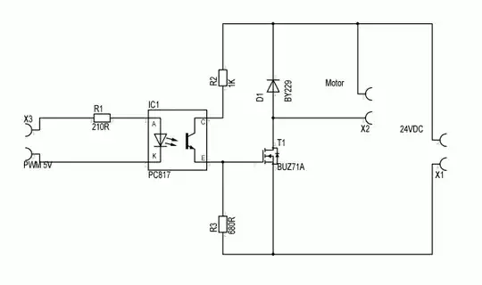
Replace BUZ71A with MOSFET of your choice as above.
Input:
Either: X3 is the input from the microcontroller. This is driven high for on and low for off. "PWM5V" is grounded.
Or: X3 is connected to Vcc. PWM5V is driven by the microcontroller pin - low = on, high = off.
As shown \$R1 = 270 \Omega\$.
Current is \$ I= \frac{(Vcc-1.4)}{R1}\$
or Resistor is \$ R = \frac{(Vcc-1.4)}{I} \$
For Vcc = 5V and \$270 \Omega\$ I here =~ 13 mA. If you wanted say 10 mA then \$R = \frac{(5V-1.4V)}{10mA} = 360 \Omega\$ - say 330R
Output:
R3 pulls FET gate to ground when off. By itself 1K to 10k would be OK - Value affects turn off time but not too important for static drive. BUT we wil use it here to make a voltage divider to reduce FET gate voltage when on. So, make R3 the same value as R2 - see next paragraph.
R2 is shown gointo +24 Vdc but this is too high for the FET maximum gate rating. Taking it to +12 Vdc would be good and +5Vdc would be OK if the logic gate FETs mentioned are used. BUT here I will use 24 Vdc and use R2 + R3 to divided the supply voltage by 2 to limit Vgate to a safe value for the FET.
R2 sets the FET gate capacitor charge current. Set R2 = 2k2 gives ~10 mA drive. Set R3 = R2 as above.
Also, add a 15V zener across R3, cathode to FET gate, Anode o ground, This provides. gate protection against over voltage transients.
The motor connects as shown.
D1 MUST be included - this provides protection against the back emf spike which occurs when the motor is turned off. Without this the system will die almost instantly. The BY229 diode shown is OK but is overkill. Any 2A or greater current rated diode will do. An RL204 is just one of a vast range of diodes that would suit. A high speed diode here may help slightly but is not essential.
Switching speed : As shown the circuit is suitable for on/off control or slow PWM. Anything up to about 10 kHz should work OK./ For faster PWM a properly designed driver is required.
Russell McMahon
- 147,325
- 18
- 210
- 386
-
@Madmanguruman - great spruce-up job! – stevenvh Jul 20 '11 at 14:45
-
1I guess I'm a little OCD when it comes to posts without math markup... – Adam Lawrence Jul 20 '11 at 16:24
-
OCD you say? Hmmm. It may look OK to you guys - all I see is a munted mess where my equations were. Presumably what would have been readable to all viewers before is now gibberish for me and an unknown number of other users. I'm using Chrome - checks with IE - yep looks OK in IE. What you have done is to take something cobby but universal and replace it with something which is browser specific. Presumably this is yet another advantage of the Wiki approach. – Russell McMahon Jul 20 '11 at 16:39
-
Any chance that some suitably obsessive person will see fit to make this browser non-specific or change it back again? – Russell McMahon Jul 20 '11 at 16:42
-
@Russell - At first it didn't work for me either, until I found that the NoScript plug-in for Firefox blocked the **mathjax.org** domain. Maybe Chrome does something like that. If you don't like an edit, you can always **rollback**: click on the date/time indication next to the word "edited" under your post. – stevenvh Jul 20 '11 at 17:51
-
@Russell - According to [mathjax.org](http://www.mathjax.org/resources/browser-compatibility/) it should be compatible with Chrome. – stevenvh Jul 20 '11 at 18:31
-
Agh!!! It's working now? What happened. No reboot here. Strange. – Russell McMahon Jul 21 '11 at 03:17
-
@Russell - Where the best place to put an LED that indicates the on/off state of the motor? – m.Alin Aug 02 '11 at 20:43
-
1If plenty of input drive and if motor is mainly on/off then duplicate R1 and LED in coupler and place in parallel with them. OR R + LED across motor with suitably large R. eg for 5 mA LED current R ~= 4k7, Rdissipation ~= 1/8th Watt so use 1/4 W or 1/2 W R. Place a reverse diode across LED "just in case" for motor transistent. – Russell McMahon Aug 03 '11 at 02:32
-
2 Questions: 1) If the motor was using 10V instead of 24V, could we do away with R2 altogether?---and just add another resistor from Emitter to Gate, sized according to max collector current, to be the gate driver? What confuses me is that if this were a standard NPN BJT transistor instead of an optocoupler, you'd have to get rid of R3 and make this an inverting driver. 2) Can optocouplers we wired like PNP OR NPN transistors, and be *either* inverting *or* non-inverting? – Gabriel Staples Jan 19 '16 at 21:56
-
@GabrielStaples you can eliminate R2 in that case BUT note my comment about limiting charge rate of Cgate to SLOW switching speed. Opto may do that anyway. || I think your inverting / non inverting query is covered by my answer at "Input:". I explain there that it can be done either way. If X3 goes to say 5V+ then PWM low turns opto on. If pin now shown as PWM in is grounded and PWM is applied to X3 then high drive turns it on. ie either polarity selectable. THe diode being able to be driven from either end with the other end being connected appropriately is what gives you this extra feature. – Russell McMahon Jan 20 '16 at 16:53
-
@GabrielStaples Read slowly and carefully through the drive section and look at diagram and it should become clear. If not find my typo and advise me :-). – Russell McMahon Jan 20 '16 at 16:54
9
As far as the MOSFET is concerned, an optocoupler is just a transistor.
As far as the microcontroller is concerned, an optocoupler is just an LED.
So, all you need is a normal transistor-driven MOSFET circuit, and a normal microcontroller-driven LED circuit.
Here's an example of driving a MOSFET with a transistor:
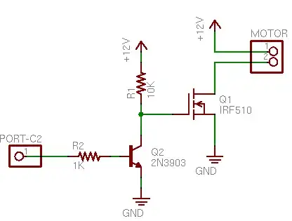
So Q2 is the output side of the opto-couper. R2 would be replaced by the input LED side of the opto-coupler and it's current limiting resistor.
Majenko
- 55,955
- 9
- 105
- 187
-
My main concern was how to drive the MOSFET, as I never worked with one.. If I need extra resistors, if the MOSFET is 0 or 1 activated.. – m.Alin Jul 20 '11 at 09:10
-
-
2@m.Alin - This is a bit confusing, because you won't be driving the transistor's base (like you said), but also because it's inverting: if your I/O pin is high the MOSFET will be off! I explain another way (non-inverting) to connect it in my answer. – stevenvh Jul 20 '11 at 09:26
-
This is true, but it's pretty much the only example I could find on the net. I could draw my own, but I'm bust breadboarding at the moment. – Majenko Jul 20 '11 at 10:37
-
@Majenko I want to ask two things: 1) This scheme is inverting; would it be non-inverting if we choose a PNP for Q2 and connect it to the high side and connect R1 to the low side? 2) This is a motor driving application, and I assume that on/off speed of Q1 is not necessary to be too high. So, why don't we drive Q1 directly from PORT-C2 over R2 resistor? Q2 is just for speeding up, isn't it; is there any other reason for adding up Q2 to the schematic? – hkBattousai Sep 14 '11 at 18:17
-
Q2 is there to a) invert the signal, and b) provide a higher switching voltage to the FET. If you choose a different FET you can have a lower switching voltage and do away with Q2 altogether. – Majenko Sep 14 '11 at 18:26
-
However, Q2 in this example is a placeholder for your optocoupler. You could easilly switch it around to give non-inverting with a PNP instead. – Majenko Sep 14 '11 at 18:28
-
Inverting is a non-issue imho. Thanks for this example. I am curious, though, about a motor being the load. Of course, there are several kinds, but wouldn't any kind of motor introduce spikes in the current draw that could overload the MOSFET? – SDsolar Sep 25 '17 at 08:19
6
The optocoupler's isolation gives you the advantage that you can place its output transistor anywhere you like, independent of the microcontroller's supply voltage.
Driving the opto-coupler means driving its LED. If the microcontroller can't drive it directly you'll need a small transistor for that.
Next you place the optocoupler's output transistor to the MOSFET: collector on V+, emitter on the gate. Place a resistor between gate and ground. This way you'll switch the MOSFET's gate between V+ and ground. The MOSFET doesn't need the 24V to switch 6A, however, 5V is enough. You can limit the gate voltage by having a resistor in series with the optocoupler's transistor. If the transistor to ground is 4k7 you can pick 10k for this.
If the optocoupler's LED is on the transistor will conduct and make the gate high, switching the MOSFET on. If the LED is off, the transistor will be off, and the gate will be pulled low by the resistor.
stevenvh
- 145,145
- 21
- 455
- 667
-
4
-
Completely applicable, specially for not reversing relationship between opto's status and MOSFET'. However, it should perhaps be better to contain a schematic. – Pana Jul 30 '19 at 11:27