1

schematic

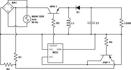
simulate this circuit – Schematic created using CircuitLab

I have designed this circuit based on a buck converter. I'm just having trouble finding out which values to plug in. I.E. C1, L1, and the frequency for the output of MCU.

Also, as this will be my first PSU, I wanted to get some circuit analysis before I plug this into the main.

Note that I realize the output of the buck converter will have to be turned back into AC, and run through a transformer to isolate the circuit, then turned back into DC.

Un-Specified Components:

This is a theoretical circuit, thus I have I have not committed the values and specificity of the components. My question is whether this circuit could theoretically work, and how to select components for certain voltage values on the output.

Intended Operation:

BR1: This bridge rectifier turns the main's AC into DC.

Voltage Divider R1-R2: The resistance values are undefined because I have not selected a microcontroller for MCU. The voltage here will be dependent on the needs of the micro-controller I eventually select as MCU.

MCU: A microcontroller which will turn the NPN 1 on and off to form the cycles for the buck converter. MCU's VCC is connected to a transistor (PNP 1). The function of PNP 1 can be defined as: IF there is no current coming from the buck converter, then the MCU is powered by the voltage divider R1-R2. This is because I would rather use the more stable buck converter's voltage to power the MCU than the unstable voltage through the voltage divider. The MCU will only be powered through the voltage divider until the first cycle begins.

NPN 1, L1, C1, D1, Load: This circuit constitutes a straight forward, run of the mill, buck circuit, with NPN 1 being used as the switch, fired by MCU.

Application of This Power Supply:

I'm building a 3-in-1 laser engraver, 3D printer, and CNC machine. I've built a prototype with a working area of 35mm x 35mm x 35mm. However, the prototype runs off of a Raspberry Pi, 3 dual-h-bridge modules , and a laser driver circuit. The end goal is to apply the code I wrote for the prototype to a completely scratch-built printer. The printer will require 9V at varying current loads. (I.E. the device driver needs more current to power a high torque CNC router than the 3D plastic extruder.)

Allenph
  • 707
  • 3
  • 12
  • 32
  • 4
    It's commendable that you are attempting this but (1) What you re trying can be lethally dangerous and it is not the right starting point. (2) Your circuit has inadequate information to get a useful answers and it is drawn so badly that even very experienced pople will have troub;e working out what you are trying to do amnd what mitakes have been made. | You cannot just say "U1", provide no details and not all connections. Your transistors are not driven realistically. None of your transistors are connected in a way that suggests they will do anything useful.... – Russell McMahon May 17 '15 at 09:08
  • ... |If you are serious about learning start with a low voltage AC powered circuit (say 12 VAC in). Look up all the application notes and data sheets for a MC34063 and start with that. Flexible and cheap. | If you do not improve the digram and question asap the people who do such things WILL put it on holdor close it. – Russell McMahon May 17 '15 at 09:11
  • Well, the whole reason I got into electrical engineering is to build a very specific project. It hinges on the power supply. I should have detailed the function of U1. I will add that momentarily. I will also add a circuit explanation. My apologies for the sub-par circuit drawing. – Allenph May 17 '15 at 09:11
  • 1
    Agreed with @RussellMcMahon. For others to understand a circuit diagram it helps if you discuss its intended operation. Also, the load is missing. Draw it as a resistor. – jippie May 17 '15 at 09:11
  • Base resistors are not optional - please put them in. Q1 is backwards. This is a total mess. – Andy aka May 17 '15 at 09:22
  • Maybe this can be of some help: http://electronics.stackexchange.com/questions/28251/rules-and-guidelines-for-drawing-good-schematics Your circuit layout can use some ironing. – jippie May 17 '15 at 09:30
  • Stop. Just stop. Learn how to connect and operate a single transistor. Then come back to this circuit and you'll see it's completely wrong - even after connecting NPN2 the right way round, it's now an emitter follower which really won't do what you want. –  May 17 '15 at 09:30
  • I have made edits to accommodate your critique. I apologize for the errors in the circuit drawing. Circuit explanation has been added. @Andy aka, I'm afraid I don't know what you mean by "base resistors." – Allenph May 17 '15 at 09:31
  • I have completely redrawn the circuit. It's a lot easier to read now. Please keep in mind that this is a fundamental drawing, and the question insinuates that this *probably will not work* the question is asking why that would be the case, if it is. Please try and take it easy. – Allenph May 17 '15 at 10:29
  • @Andy aka, I have added the base resistors. However, their values are undefined for similar reasons to those detailed in my question. – Allenph May 17 '15 at 10:37
  • Your diagram is MUCH better (but still conceptually wrong - see below). **BUT** my original point (1) is stll crucially applicable - ie "(1) What you re trying can be lethally dangerous and it is not the right starting point" - You are unab;e to change this - what you are doing is potentially fatal to you or the circuit or both. It will be vastly more valuable to yourself (and safer) to start off with a probably cheap effective known design that teaches you the basic principles. Trying to design and build a discrete component off line switcher is somewhat akin to learn to drive in ... – Russell McMahon May 17 '15 at 17:21
  • an Indy 500 race car in mid level competition. Not only much harder than necessary but makes minimal sense and endangers yourself and others. Pleasing "just theoretical" is not good enough. It's not what your question actually says and doing it offline adds issues which are not needed when learning. Doing it discretely also adds issues of hardness and ADDS complexity you do not need and will not benefit from. FWIW - I have implemented fully discrete buck regulators with 200V+ input and 12V output in a production situation - I assure you that that is not where you want to start :-). So ... – Russell McMahon May 17 '15 at 17:26
  • re " ... Well, the whole reason I got into electrical engineering is to build a very specific project. It hinges on the power supply. ..." -> **THEN** you need to very specifically tell us about your requirement. It is extremely hard to imagine that a very specific project that is important to you hinges on you taking the approach that you are. If you need to power a low voltage circuit from main AC then there are a very large number of circuits or approaches that you could use that are superior to what you are trying. If you have a need that justifies this approach then we need to know it. – Russell McMahon May 17 '15 at 18:42
  • 2
    I'm voting to close this question as off-topic because it requires too much correcting and learning by the op to get the question to a minimal decent standard. – Andy aka May 17 '15 at 19:29
  • @Andyaka You need to get out of bed on the OTHER side (again) :-) ) | Damned if he does. Damned if he doesn't. No? The idea is that bad questions should be improved. This has improved immensely | This started off as a vey closable questsion BUT has evolved reasonably well into something that can serve as an education for others as well as the OP. If your comment had been made early on then maybe OK. But if you think questions like this should be closed there is an awfully large amount of other housekeeping needed here. – Russell McMahon May 17 '15 at 23:48
  • OK. Listen .... STOP. If the application of this power supply is as you say and if you want the project to work, this is not the way to do it. Even if this worked perfectly it would not be what you want or need for your project. Yhe reasons are already covered in comments and my answer. The most logical (and cheapest) path is to find an existing power supply that meets your need. Then once your main project works properly come back to making your own power supply if you still want to. It needs to be isolated with a properly related transformer - this is a sensible, ethical and regulatory ... – Russell McMahon May 18 '15 at 02:14
  • ... requirement. It should not be a wide conversion voltage range buck converter* as there are too many problems and other ways are easier and better. It needs you to know quite a alot more than you do - needing to learn is fine - but this design is not the one you want to learn about or learn on. || *-Wide conversion ratio buck converters can be implemented but the need has to justify the complexities faced. In this case it doesn't. I had an application where Vout:Vin varied from 1:1 to over 17:1 and I needed ultra low cost. A buck converter made sense in that case - but its very unusual. – Russell McMahon May 18 '15 at 02:20

3 Answers3

3

You didn't say what the power supply will be powering, i.e. what the output voltage and current are. Thus, it's not clear that a switching converter is really the best solution to your problem. A simple linear regulator or even unregulated rectified AC might be good enough. Without knowing the voltage and current it's impossible to recommend a topology, much less component values.

As others have noted, your circuit has a lot of problems. Here's are the ones I noticed. There may be more.

  1. The overall topology is that of an inverting buck-boost converter, not a non-inverting buck converter.

  2. You're using the rectified mains voltage (~170V) directly to get an output that's probably in the range of 5V. With a buck converter, that gives a duty cycle of ~3%, which is probably too low to control effectively. Also, your rectified input supply does not have a capacitor. Finally, there's no isolation between the mains and the output, which means that a fault could be lethal. This is not something you should ignore. Imagine your family and friends standing around your grave in tears, and their only consolation is the smoking remains of a crappy power supply.

  3. Powering an MCU via a voltage divider is questionable at best. Powering an MCU from the output side of the thing it's regulating is extremely questionable. MCUs like stable voltages, and misbehave if they don't get them.

  4. Your MCU cannot drive the switching transistor directly, since its output signal will be at the same level as the output voltage, thus making \$V_{BE} = 0\$. Also, MOSFETs are usually better than BJTs for this application.

  5. Feedback control is a pretty big subject. You can make a nice career out of implementing and tweaking control systems for power supplies. If you're not familiar with control theory, you probably won't want to deal with it as part of another project you're already having trouble with. Errors in the control algorithm for a high-voltage circuit can be lethal.

  6. The MCUs feedback input and VCC are both grounded.

Here's what I recommend you do:

  • Consider using a wall-wart instead of designing your own power supply. It will save you a lot of trouble.

  • If you must design your own supply, put a transformer on the input to reduce the voltage and isolate the circuit from the mains. Be sure to use a fuse and insulate all exposed high-voltage conductors.

  • Unless you need high efficiency (>80%), try using a linear regulator like a 7805 or LM317. An LDO will let you reduce your transformer output voltage for greater efficiency.

  • If you really need a switch-mode power supply, get an integrated converter like the one Russell mentioned. The datasheet will tell you what component values to use. You can also find modular power supplies that include all components. Or you could even copy an existing circuit without modification.

  • If you insist on designing your own switch-mode power supply from scratch, you will need to learn a lot more. For background knowledge, you'll need at least a bachelor's degree worth of EE education. This Coursera class can teach you about the basics of SMPS design and control systems. (I think you can do it even when there are no sessions scheduled.) Or you can find a textbook, or take a class at a local college.

This is a major project, not a stepping stone.

Adam Haun
  • 21,331
  • 4
  • 50
  • 91
  • I've added the application of the power supply in order to receive educated input on power supply typography. – Allenph May 17 '15 at 22:20
  • @Allenph Can you be more specific about how much current is required? – Adam Haun May 18 '15 at 05:43
  • I haven't selected the motors yet. But, they're going tobe very high torque. Not more than 1A and not less that 500mA. – Allenph May 18 '15 at 06:08
  • You can easily find 9V 2A AC adapters on Amazon. I'd suggest going with one of those. 2A linear regulators are also easy to find. – Adam Haun May 18 '15 at 13:39
2

Your circuit shows a good attempt at trying to understand concepts of discrete offline switching power supply operation. It is however a very long way from the concepts that are being learned to implementing a practical design. It would not be impossible to keep hammering away at this design until all the misunderstandings bugs and errors were hammered out of it and necessary practical aspects added BUT this is not the best way to learn to do this and is costly on your time and effort, and on the time and effort of others, and may kill you along the way and will certainly kill various versions of the circuit if ever implemented.

If you look at the available circuits you will find that almost nobody implements direct off-line buck converters. It is sometimes stated that the conversion ratios required cannot be implemented with a single stage buck converter. While it is doable* it is usually not practical, sensible or safe.

I have noted and the end of this answer a few of the issues that this circuit has, as shown in the latest version. The new diagram is a vast improvement over the original but is still a long way from looking like a circuit that would even try to operate.

If you keep attempting this incremental path you will end up having to address issues which are not fundamental to the basics of what you are trying to do and you will miss out on learning about more basic issues that are important. Laying this circuit aside for now and starting with

  • A low voltage input switching power supply

  • Using a cheap readily available conceptually simple(but still very capable) IC

would be a much more productive approach.

I often recommend a very old & low cost control IC which is still very useful.
Unlike some potentially better performing modern ICs it can implement almost any topology and it has an internal output switch which means it can implement complete power supplies with minimal added components up to a certain power level. This is the olde but goode MC34063

Excellent ON Semi MC34063 data sheet - has basic circuits with PCB layouts and components lists.

AN920/D Superb ON Seminconductor application note 40+ pages of extremely good discussion, circuits, design information and more. They say -

  • The goal of this application note is to convey the theory of operation of the MC34063 and μA78S40, and to show the derivation of the basic first order design equations. The circuits were chosen to explore a variety of cost effective and practical solutions in designing switching converters. Another major objective is to show the ease and simplicity in designing switching converters and to remove any mystical “black magic” fears.

TI MC34063 application note reasonable. 12 pages.

Basic design calculator for inverting buck-boosttopology

A zillion circuits using it

Related:

ON SemiSwitch-mode power supply reference manual

ON Semi LED circuit solutions


These comments relate to this version of the circuit:

enter image description here

You will note on inspection that your Vcc and ground are hard connected.
This is no doubt not what you intend.

While you say that " ... This circuit constitutes a straight forward, run of the mill, buck circuit, ", it doesn't. This is one version of what is known as a buck-boost circuit. This is because the output can assume a voltage above or below the input oltage in magnitude. It achieves this clever trick at the cost of inverting the output polarity - Vout is negative if Vin in positive, which is why D1 is connected as it is. Your pocessor will not operate on a -ve Vcc and if you rearranged it so it would (uC grtound = -Vcc, uC Vdd = ground) it will then not drive NPN1 correctly, even if NPN1 was crrectly configured, which it is not.

If you reverse D1 you do not get a +ve output - you get flaming ruin. Your basic circuit is not correct. D1 and L1 need to be interchanged with correct polarity on D1 for the new topology.

NPN1 need to be a PNP (or some other device) and driving it from a uC (above or below ground) takes substantially more than a drive resistor. While the diagram can be seen as conceptual there is not too much detail that is just plain wrong.

The intended operation of PNP1 is understood but you need much more "glue"components than are shown, and as shown, R1 & R2 will dissipate substantial ongoing energy when PNP1 is off (about 150 mW per mA of startup load so say around 1.5W for at 10 mA startup load.)

To convert this circuit into something that works safely, reliably or at all would require a long and unnecessary journey.

Russell McMahon
  • 147,325
  • 18
  • 210
  • 386
  • I've added the application of the power supply in order to receive educated input on power supply typography. – Allenph May 17 '15 at 22:20
1

This is a simplified version of the circuit you have. Note the polarity is backwards from your circuit:

enter image description here

tcrosley
  • 47,708
  • 5
  • 97
  • 161
  • He could take a look at LTSpice, http://www.linear.com/designtools/software/%23LTspice which includes many sample circuits that can be simulated, inspected, measured, and toyed with before attempting to design one. Such as the http://www.linear.com/product/LT3724 for example. As others have said, just stay clear away from rectifying mains voltage. Use a transformer (always) and before the rectifier, not after. – rdtsc May 17 '15 at 20:27