There are a couple things that need to go with looking at how opamps work with negative feedback.
- Very high input impedance, so essentially no current flow into the terminals.
- The opamp will do all that it can do ensure that the inverting and non inverting terminals are at the same voltage. (V+ - V- = 0)
Consider the following.
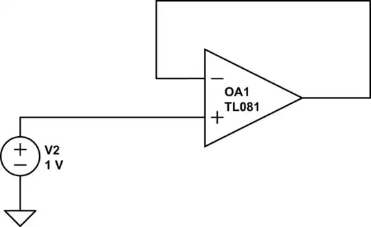
simulate this circuit – Schematic created using CircuitLab
This does not have any feedback. We have 1V on the non inverting terminal and the inverting terminal is grounded. The opamp, will do everything it can to make sure that the terminals are at the same potential. So the opamp is going to increase its voltage in the hopes that the negative terminal will balance out, so that the difference between the two terminals is zero. But, because there is no feedback, the opamp's "efforts" are in vain and the output just increases until you reach the limit of the opamp. It's trying, but nothing it does can bring the terminal voltages to be the same.
simulate this circuit
In this case, the opamp has feedback. So as the output voltage changes, the voltage at negative terminal changes. When a balance is found, the opamp maintains that voltage. If the input changes, the opamp will then find what the new balance is. All because it wants to make sure that the voltage at the terminals is 0V. (V+ - V- = 0)
This is all great, but what if want gain ? Right now, the output will change so that it matches the input, and for a buffer, that's great but its not useful if you have a low voltage signal that you want to boost up to something more readable.
And this is where feedback resistors come into play.
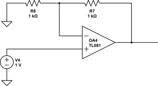
simulate this circuit
Remember the rules ?
Opamp will do everything it can to make sure the inverting and non inverting terminals are the same.
Let's see what happens now.
We have a 1V signal. If the opamp outputs 1V, then the voltage seen at the inverting terminal is only 0.5V. But the opamp is not "happy" at this because it want's the difference to be 0. So it increases the voltage. When the opamp increases the voltage to 2V, then the inverting terminal sees 1V. The opamp is happy. So we fed in 1V, and we got 2V outs, this is a gain of 2.
So feedback resistors are used to attenuate the voltage at at the inverting terminal from the output to trick the output terminal to produce a larger voltage.