Please take a moment to look at the three-phase Y and Delta configurations pictures below (The pictures are screenshots taken from the “All About Circuits” online book).
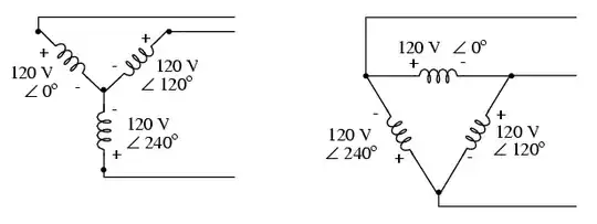
The first picture (Y configuration) shows the neutral node with negative polarities for all phases and the outside nodes with positive polarities for all phases. The second picture (Delta configuration) shows opposing polarities between the consecutive phases (plus, minus, plus, minus, plus minus clockwise rotation).
My questions revolve around the phase polarities as follows:
1) On the Y configuration, you can see that the author of the drawings labeled the neutral node with negative polarities for all phases. Given that AC voltage constantly changes polarities, why is he deliberately labeling the node with a fixed minus sing? The same goes for the outside nodes, why is he labeling them with fixed plus sings when those polarities are also constantly changing?
2) The other reason why all minuses and all plusses don’t make sense in my head has to do with phase shift. If all phases on a three-phase power are spaced 120 degrees apart from each other, there should be no way for all phases to have the same polarity at all times correct? In other words, it should be impossible for all phases to always be positive or always be negative. At one point in time or another, some will be positive and some will be negative correct?
Anyway, I am pretty sure that I am totally missing the point of what the diagrams are trying to convey so I was hoping someone could help me get a clue.
Thank you.