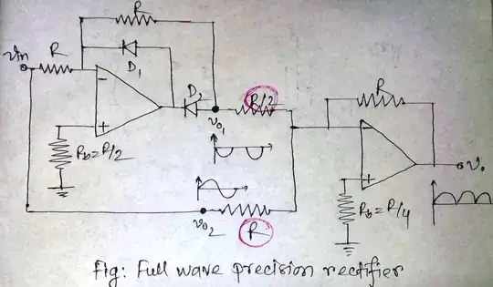
The first part of the circuit, whose output is \$v_{o1}\$, is a halfwave precision rectifier.
For the positive half of the input, the diode D2 will be forward biased and D1 will be reverse biased. So it acts as an inverting amplifier with unity gain. So \$v_{o1}\$ will be inverted version of input for positive half cycle. ie, \$v_{01} = -v_{in}\$ for positive half of input.
For the negative half, diode D1 will be forward biased and D2 will be reverse biased and hence \$v_{o1}\$ will be zero for negative half cycle. ie, \$v_{01} = 0\$ for negative half of input
The second part of the circuit is a summing amplifier whose output is given by:
$$v_o = -\left(\frac{R}{R/2}v_{o1} + \frac{R}{R}v_{o2}\right) = -(2v_{o1}+v_{o2})$$
where \$v_{o2}\$ is the input.
For positive half of input, \$v_{o1}=-v_{in}\$ and \$v_{o2}=v_{in}\$. Hence \$v_o = v_{in}\$
For negative half of input, \$v_{o1}=0\$ and \$v_{o2}=v_{in}\$. Hence \$v_o = -v_{in}\$
And this is the input output relation for a full-wave rectifier. The resistor values R and R/2 are chosen deliberately to obtain this input-output relationship.