In the circuit below (schematic diagram), the command from a microcontroller allow to send the 5V to the output through two transistors command Q1 and Q2.
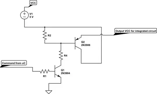
simulate this circuit – Schematic created using CircuitLab
My question is: what happen if the transistor Q1 is short circuit, the output can be energized even if the command from the microcontroller is off ?