0

There is a question here about something similar, but it's asking about the internals of an op-amp. I'm having trouble understanding the function and use despite several hours of YouTube tutorials.

schematic

simulate this circuit – Schematic created using CircuitLab

I'm having an awful time figuring out how this works...and EXACTLY what it does.

From what I understand:

1) Op-Amps compare the voltage between the non-inverting input and the inverting input, then multiply the difference by an almost infinite number and that product becomes the output. (I.E. Gain)
2) The inputs neither draw nor output any current.

This configuration should make it so that the inputs are always at the same voltage.

I'm not sure I understand the purpose of this configuration, and I certainly don't understand how negative feedback works to produce that effect on the inputs.

Allenph
  • 707
  • 3
  • 12
  • 32
  • Maybe it works better when instead of infinite gain you think about it like "puts onto output whatever is needed to make both inputs being equal"? – PlasmaHH May 12 '15 at 11:00
  • That helps a lot actually. I'm still having trouble understanding how it works...not neccesarily the internal circuitry, but why the addition of those two resistors causes what you mentioned in your comment to occur... – Allenph May 12 '15 at 11:02
  • The configuration you show is pretty easy to understand. The + terminal is grounded, and r2/r1 form a voltage divider. If the "input" node is driven high by external circuitry, the op-amp will force its output negative until the voltage at the - terminal is approximately equal to the voltage at the + terminal (i.e., to ground). Current will flow from the input, through R2 and R1, and in to the op-amp's output terminal. The opposite happens if the input is driven low. – Solomon Slow May 12 '15 at 13:38
  • 1
    Step 1 in understanding technical things: Use written reference materials with drawings, pictures, and diagrams instead of watching vague "tutorial videos" on YouTube. YouTube is great for funny cat videos, but that's about it. – JRE May 12 '15 at 13:40

4 Answers4

1

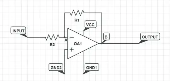
Allenph - to understand the "secrets" of negative feedback you should not complicate things by applying unsymmetric supply voltages. The classical bipolar operation is based on dual supply voltages. Therefore, replace GND1 by -Vcc.

Now - let`s take another example: R1=2k and R2=1k. What will happen with Vin=1 Volt?

1.) At first (because the opamp cannot react without time delay) the output voltage will be either at +Vcc or -Vcc (supply voltages switched on) Lets assume Vout(t=0)=-Vcc=-6 V.

2.) It is simple to calculate (superposition rule) that the voltage at the inverting terminal will be Vn(t=0)=1*2/3 - 6*1/3=-4/3 V.

3.) Hence, Vn is negative and because of the inverting operation of the opamp the output voltage tends to go to positive values (less negative). As a consequence, the Vn voltage also will rise (from negative to positive values).

4.) However, between the starting value of Vn(t=0)=-4/3 V and any positive values there will be one single positive value for Vn(t) (in the µV range) which fulfills the equation Vout(t)=Vn(t)*Ao (Ao is the opamps open-loop gain). In this context, it is important to realize that there is no "switching" action - the voltage Vout changes its value in a short - but finite - time!

5.) Now, the opamp is in LINEAR operation at a point which is the only one that fulfills the above equation. Hence, we have a state of equilibrium which gives a fixed output voltage.

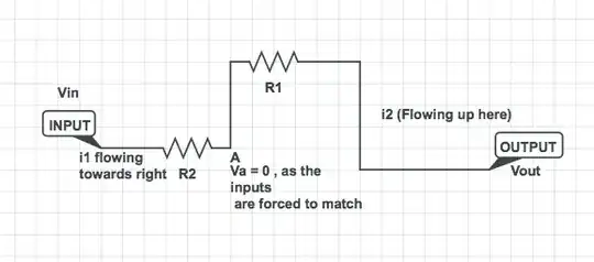
6.) For calculation of this output voltage (bias point) we neglect the Microvolts at Vn at set Vn=0 (virtual ground principle).

7) Now, it is easy to find the output voltage Vout for the given values (Vin=1V, Vn=0, R1/R2=2): Vout=-2V.

8.) Thus, we have a gain of G=-R1/R2=-2 (assuming opamp ideal with Ao infinite).

Comment: If you would set Vn=...µV instead of Vn=0 the difference between both results would be less than the real tolerances of the resistors.

LvW
  • 24,857
  • 2
  • 23
  • 52
1

I will just give it a shot, and hope it can make it easier for you to understand.

Now you know that an Op-Amp essentially multiplies the difference between the 2 input by an infinite gain . So if the circuit had been without a feedback then theoretically output =G(V1-V2) - G is the gain .

Since in circuits we do not wish to use it for an infinite gain, and try and use it for a finite gain say 2x, so we now need to make changes to the circuit to allow us to control the gain. The resistors that are added are essentially for that.

Now Consider the circuit from your question, I have added labels A and B to walk through.

enter image description here

Output of the circuit without feedback, will be

Vout = G(Vin)

Now since we feed that output back to the input through the a voltage divider . there will be some changes.

Firstly , the golden rule of Op amp , that it drives the output to a voltage to have the 2 inputs to be equal, that is the A , and voltage at other input(Which is GND) . So we will have something like this

enter image description here

Now note that Voltage at A will be 0. (Inverting input will be forced to be 0 to match the input at the non-inverting terminal) . And the Currents i1(Flowing from Input through R2 to A) and i2(From Vout through R1 to A ) will add to zero.

Therefore i1 + i2 =0

ie. Vin/R2 + Vout/R1 = 0

Hence solving this, we get : Vout/Vin = -R1/R2 which is essentially the Feedback equation for this circuit.

Hope this answers what you were asking.

Sherby
  • 2,316
  • 6
  • 27
  • 44
0

Your two points are more a descriptor of a comparator than an op amp. An op amp is very similar to a comparator, but it has a voltage ramp built into the output. This way, if the non-inverting input is higher than the inverting one, the output will begin to ramp very quickly.

As far as your circuit is concerned, you can think of the op amp as "wanting" to make the two inputs equal in voltage. If + is greater than -, the op amp will ramp up, thereby increasing, and vice-versa, until + and - become equal or the op amp reaches one of its power rails.

Imagine you apply a positive voltage to the input. The - input will become greater than the +, so the output will begin to ramp down. This will continue until the value at the - input reaches 0, because you applied 0 at the positive input. If R1 is greater than R2, then the output will have to ramp to (-R1/R2) times the input to cause the two inputs to be equal. This is where the gain comes from.

tmiddlet
  • 101
  • Ha! I think I finally got it. But why do you need the resistors? – Allenph May 12 '15 at 11:54
  • Also...imagine I replaced GND2 with +5v and added +4v to the input. The inputs wouldn't be able to match through adding negative voltage... – Allenph May 12 '15 at 12:02
  • An op-amp is very basically the same thing as a comparator. The ramp you speak of is *very* steep. I don't know the details, but the difference between the ones that are labelled "op-amp" and the ones that are labelled "comparator" is subtle. You can use a "comparator" in an "op-amp" circuit, but the output may not be as linear as you would like. You can use an "op-amp" in a "comparator" circuit, but it may not switch as fast as you would like. – Solomon Slow May 12 '15 at 13:34
  • Using a comparator as a linear amplifier is "dangerous" because of stability problems. Comparators are not (and need not to be) phase-compensated. Hence, negative feedback can violate the stability criterion. – LvW May 12 '15 at 14:27
0

In general, we must speak of two types of gains: the open loop gain and closed loop gain.

The open loop gain is the same as the reference you do when you say an almost infinite number. The closed loop gain, relates to the open loop gain with the feedback network.

In the circuit that you propose, the feedback network is formed by resistors \$R_1\$ y \$R_2\$.

Basically, if \$A\$ is the open loop gain, the closed loop gain is

\$ A_f=\dfrac{A}{1+\beta\cdot A} \$

where \$\beta\$ is the transfer function of the feedback network, in this case

\$ \beta = \dfrac{R_2}{R_1+R_2} \$

If the open loop gain \$A\gg 1\$, the closed loop gain

\$ A_f\approx\dfrac{1}{\beta}=1+\dfrac{R_1}{R_2} \$

Conclusion: if \$A\$ is very high, the gain of the amplifier is independent of the OPAMP, and can be established by the feedback network.

Martin Petrei
  • 3,034
  • 12
  • 20
  • No one has mentioned the concept of the "virtual earth"! Point A is what is referred to as a virtual earth, it's not a real earth but is around zero volts. In this circuit configuration, the opamp acts in such a way so as to keep point A at zero volts. – Dean May 15 '15 at 18:34