I have the following power supply configuration: AC MAINS -> UPS -> 24V POWER SUPPLY -> 5V VOLTAGE REGULATOR -> PCB (microcontroller). What's the best solution to detect the power outage on the mains with the microcontroller? I also need to detect the zero-crossing so that I can control the speed of an AC motor.
Asked
Active
Viewed 1.7k times
33
-
Do you need proper isolation between the mains and the microcontroller, or can you get away with something simpler? – Jul 18 '11 at 09:30
-
8It needs to be isolated, yes. Feeding the mains to a pin of the microcontroller through a large resistor isn't a solution for this project.. – m.Alin Jul 18 '11 at 09:41
-
6Why is m.Alin's comment upvoted, twice? He's just giving more information. Or do the upvoters think that from 230V to a microcontroller's pin is never done, and do they think it's a good joke? – stevenvh Jul 18 '11 at 16:41
-
4Have the microcontroller watch its own power, and when the power goes away have it send --- Oh, right, nevermind. – Olin Lathrop Jul 15 '12 at 12:25
-
@OlinLathrop Good idea! But can I use a 555 instead of a microcontroller? :-) – m.Alin Jul 15 '12 at 12:54
-
1@OlinLathrop: that's the proverbial product manager asking for a LED that has to go on to warn when the battery is low. – pebbles Dec 12 '13 at 13:24
3 Answers
56
Since you also need the zero-crossing you'll get the power outage detection virtually for free.
Best is to use an optocoupler to detect zero-crossings. Put the mains voltage via high resistance resistors to the input of the optocoupler. Vishay's SFH6206 has two LEDs in anti-parallel, so it works over the full cycle of the mains voltage.
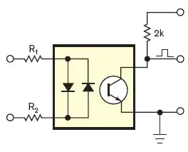
If the input voltage is high enough the output transistor is switched on, and the collector is at a low level. Around the zero crossing, however, the input voltage is too low to activate the output transistor and its collector will be pulled high. So you get a positive pulse at every zero crossing. The pulse width depends on the LEDs' current. Never mind if it's more than 10% duty cycle (1ms at 50Hz). It will be symmetrical about the actual zero-crossing, so the exact point is in the middle of the pulse.
To detect power outages you (re)start a timer on every zero-crossing, with a timeout at 2.5 half cycles. Best practice is to let the pulse generate an interrupt. As long as the power is present the timer will be restarted every half cycle and never time out. Upon a power outage however, it will timeout after a bit longer than a cycle, and you can take the appropriate action. (The timeout value is longer than 2 half cycles, so that a spike on 1 zero-crossing causing a missed pulse won't give you a false warning.)
If you create a software timer it won't cost you anything, but you can also use a retriggerable monostable multivibrator (MMV), for instance with an LM555.
note: depending on your mains voltage and the resistor type you may need to place two resistors in series for the optocoupler, because the high voltage may cause a single resistor to breakdown. For 230V AC I've used three 1206 resistors in series for this.
Q & A time! (from comments, this is extra, in case you want more)
Q: And the input LEDs of the optocoupler will work at 230V? The datasheet states that the forward voltage is 1.65V.
A: Like for a common diode the voltage over a LED is more or less constant, no matter what your supply voltage is. The mandatory series resistor will take the voltage difference between power supply and LED voltage. The answers to this question explain how to calculate the resistor's value. Extreme example: a 10 000V power supply for a 2V LED. Voltage over the resistor: 10 000V - 2V = 9 998V. You want 20mA? Then the resistor is \$\frac{9 998V}{20mA}\$ = 499.9k\$\Omega\$. That's 500k, that's even reasonable. Yet, you can't use an ordinary resistor here. Why not? Firstly, a common 1/4W PTH resistor is rated at 250V, and will definitely breakdown at 10 000V, so you'll have to use 40 resistors in series to distribute the high voltage. Secondly, and worse, the power that the resistor would have to dissipate is \$P = V \times I = 9 998V \times 20mA = 199.96W\$, a lot more than the rated 1/4W. So to cope with the power we'll even need 800 resistors. OK, 10kV is extreme, but the example shows that you can use any voltage for a LED, so 230V is also possible. It's just a matter of using enough and the right type of resistors.
Q: How does the reverse voltage affect the lifetime of the LEDs?
A: The second, anti-parallel LED takes care of that by ensuring that the reverse voltage over the other LED can't become higher than its own forward voltage. And that's a good thing, because a reverse voltage of 325V\$_P\$ would kill any LED (most likely explode), just like any signal diode, by the way. The best way to protect it is a diode in anti-parallel.
Q: Won't the resistors dissipate a lot of heat?
A: Well, let's see. If we assume 1mA through the resistors and ignore the LED voltage, we have \$P = V \times I = 230V_{RMS} \times 1mA = 230mW\$, so even a 1206 can handle that. And remember, we're using more than 1 resistor, so we're safe if we can work with 1mA (The SFH6206 has a high CTR \$-\$ Current Transfer Ratio).
-
@stevenvh How does the reverse voltage affect the lifetime of the LEDs? Or does the 2 LEDs in anti-parallel mitigate that problem? – Majenko Jul 18 '11 at 10:25
-
You need Ohms law. \$V=\frac{I}{R}\$ - see http://electronics.stackexchange.com/questions/14852/how-do-i-calculate-the-resistor-value-for-a-simple-led-circuit – Majenko Jul 18 '11 at 10:26
-
I've integrated questions here and the answers in a Q&A in my answer. – stevenvh Jul 18 '11 at 11:19
-
@stevenvh, this answer is too detailed and covers too many examples, I got tired and just upvoted instead of reading. I need you to start putting an executive summary at the top telling me what I am about to not read. : ) – Kortuk Jul 18 '11 at 13:15
-
1@Kortuk - I thought the title **Q & A** made it clear that those were extra information 'for the interested reader' :-). I'll highlight each question so that you can skip the ones you're not interested in. – stevenvh Jul 18 '11 at 13:20
-
@stevenvh, I meant that as a joke. It was a great answer. Hell, I actually really like the bolding also. Double win. Thought you might enjoy a response from me telling you that your answer was too good. – Kortuk Jul 18 '11 at 13:27
-
@stevenvh: If the resistors are sized to let 1mA through the LED at peak voltage, that would suggest that it won't let through anywhere near that much around the zero crossing. I wonder if it might be better to use a bridge rectifier and a transistor circuit to limit current to 1mA independent of voltage, or else perhaps a pair of circuits and a pair of optos, to detect positive and negative line phases separately? – supercat Jul 18 '11 at 16:16
-
@supercat - of course the current varies a lot, and I remember it took me quite some calculating to get decent pulses to my uC, but in the end I had pulses less than 10% duty cycle, and perfectly symmetrical about the zero-crossing. With only series resistors. The 1mA was just a guesstimate. – stevenvh Jul 18 '11 at 16:26
-
@stevenvh: If 10%-duty cycle pulses are adequate, that's fine. One might be able to effectively guess where the zero crossing is by assuming it will be in the middle of the "low" region. I would be a bit concerned that harmonic distortion on the power line might cause one's detection to be early or late, or that fluctuations in line voltage might cause things to be dicey. Depends upon the application I guess. – supercat Jul 18 '11 at 16:39
-
@supercat - dealing with noise in the signal is a business in itself. A colleague of mine designed dimmers in which the microcontroller kept perfect sync with the mains phase, no matter what trash was added to it. Kept working smoothly where all competitors' products started to flicker. Really impressive, a fine engineer. – stevenvh Jul 18 '11 at 16:48
-
@stevenvh: Monitoring line phase so the processor knows what to "expect" and when to expect it is a fine concept. My concern would be that if your device is at the end of a long extension cord, along with some other device that has a bridge rectifier and a big filter cap which, despite its size, still ripples a lot, such a device might cause yours to receive a signal that would be nice and uniform, but "late", and your device would have no way to detect such a thing. – supercat Jul 18 '11 at 16:51
-
@supercat: I think that should only be an issue if the AC at the controller is out of phase with the AC at the motor being controlled. Hopefully the wiring situation wouldn't be that problematic. Also, for noise immunity I've found it beneficial to add a resistor parallel to optocoupler diodes. It will increase the dead band around the zero crossings, but it helps prevent the diodes from being turned on by noise coupling in through the AC input lines. – Stephen Collings Jun 01 '12 at 12:36
-
Is there a reason you can't use a capacitor for the Xc at 50/60 HZ to drop the voltage, instead of turning resistors into heating elements? I'm looking at a 0.022uF cap to give me 120k Xc at 60 Hz. This is about 1.5 mA through my Optoisolator. Is there a reason this won't work? – Joe Feb 06 '13 at 21:47
-
@Joe - A capacitor would give a phase shift, so that you can't use the optocoupler to detect zero-crossings. Otherwise it's a solution to not-a-problem. 230 mW is nothing, especially when drawn from the mains, compared to a battery for instance. The capacitor will be much bigger and more expensive. So if you ignore the zero-crossing detection it would work, but it's not worth it. – stevenvh Feb 09 '13 at 10:16
-
@stevenvh We were only wanting to detect power on, not doing anything with the zero crossing, so I didn't think about the phase shift being a factor. But with 16 channels per board, the cost difference is a sizable factor. – Joe Feb 10 '13 at 23:20
-
Stable lock onto noisy mains is managed with an analogue or more often these days a digital phase locked loop (PLL). This will let you lock onto mains even if the frequency fluctuates due to mobile generator power if your PLL is smart enough to tune for changes in frequency. – KalleMP Sep 11 '19 at 06:21
3
I came across this item, an MID400 Power Line Monitor, that is designed for this purpose. The application note, https://www.fairchildsemi.com/application-notes/AN/AN-3007.pdf, gives a number of circuit suggestions, addressing several usage scenarios.
AnalogGuy
- 81
- 3
3
This has been a repeating theme with too few solutions during my upgrade of an industrial oven. Most PLCs use "AC Input" modules. In my observation, most EEs do not design with PLCs and will build an embedded device. I found a successful search phrase: control signal relay spdt slim 120v Other modifiers to include are DIN rail and Socket C.
Any kind of business with the word automation in its name will have products and literature to help with your design.
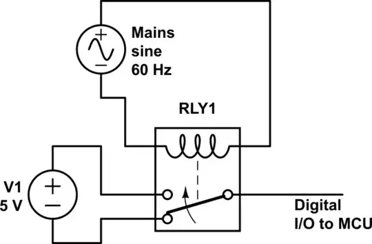
simulate this circuit – Schematic created using CircuitLab
Select the relay with input coil matching your mains supply voltage. There are coils for 100-120VAC and 200-240VAC. In my example, I chose to "reverse" the relay's output so that the digital input is always tied to HI or LO and not left floating.
The above circuit represents what I employ for monitoring the sensors on the oven, which all are NO 115VAC switches. Compact designs improve density, hence learning about "terminal block relays".
There is a unique offering on the market with great density and a ribbon cable interface from a vendor called opto22 via their G4 family. No affiliation, not even a customer. Other solutions reaching this level of density appear to be proprietary designs to interface with PLC product lines.
Krista K
- 503
- 6
- 17