5

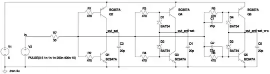
I am playing with BJT push-pull circuit from a previous question (there are 3 push-pulls with various speedup tricks for comparison):

enter image description here

I've recently realized, that's it's voltage follower, so it's not supposed to show rise/fall times shorter than ones of input signal.

Is it possible to modify it somehow to have more 'steep' output? I don't expect it to be like Schmidt trigger, just want it to have more than 1 voltage amplification near 0.5*VCC.

Is that possible? Probably some fancy level shifting, diodes...


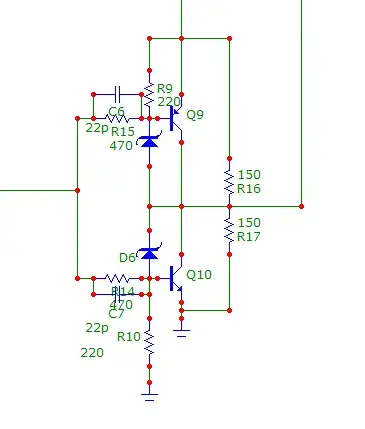
Updated circuit which gave me somewhat desired results. 150 Ohm resistors on the right are load.

enter image description here

BarsMonster
  • 3,267
  • 4
  • 45
  • 79

2 Answers2

2

Mainly an aside: Remove D3 and D4 and see what happens. These are output stage antisaturation diodes that stop the output transistors being driven into saturation so that they recover more rapidly on turn off.


Unless I am missing some inobvious linkage It consists of 3 separate circuits which are attempting to model the same thing in slightly different ways.

These are not follower circuits (according to my brain).


This may not suit what you want, but try:

Remove C3. Disconnect R3 and R4 from drive line and connect them to out_sat. Monitor out_antisat Trial.

Signal is inverted from what you had.


Next:

Add resistors from out_anti-sat to Q1 and Q2 bases. Size tbd. Say 100k to start. These provide positive feedback. Trial.

Report.

If you want rapid transition across the centreline then making each half a true Schmitt trigger (2 transistors per half) is easy and liable to be effective.

Russell McMahon
  • 147,325
  • 18
  • 210
  • 386
  • Yes, all 3 stages are voltage followers, with different speed up tricks for comparison. Removing diodes will just slow it down. I'll try to add positive feedback. – BarsMonster Jul 18 '11 at 01:33
  • Removing diodes will slow down recovery from turn on. ie they prevent the turned on stage going into saturation so that carrirs do not have to be removed before transistor can be turned off. (Which i know you know). I don't think they will affect turn on speed much. - Real world results of positive feedback in similar circuits is magic. On a number of occasions I have found that a "mere whiff" of positive feedback has transformed a circuit's ability to switch cleanly. Far more powerful in practice than may be expected. – Russell McMahon Jul 18 '11 at 01:41
2

First, these are NOT voltage followers. They are inverters. There is no reason their gain magnitude couldn't be more than 1. In fact, I expect all these circuits already amplify, but since you're putting a digital signal in you don't see the amplification when the input is near 1/2 the supply. That's probably a good thing because leaving the input there would fry the transistors rather quickly.

While the gain magnitude is most certainly above 1, it is not predictable or controlled. There are various ways to get that, like adding emitter resistors with some feedback per stage.

If you want positive gain like a Schmitt trigger, then put two of your inverters together with a little positive feedback around the pair.

Olin Lathrop
  • 310,974
  • 36
  • 428
  • 915
  • I've solved the task by adding resistors on pn junction opposite to Schottky diodes at Q3/Q4. This made my circuit have 100ns output fronts out of 1000ns input fronts, and no degradation on high speeds (5-10ns fronts). Optimal value appeared to be ~50% of base resistor. Does that make sence? – BarsMonster Aug 03 '11 at 22:38
  • As I see it, it biased transistors into region where they have higher Hfe : close to saturation Hfe is low => just 1x voltage amplification. 50% value still allow 1 transistor 'touch' saturation at the end, so I don't loose drive capability. – BarsMonster Aug 03 '11 at 22:42
  • @Bars: I'm not following what exactly you did. Perhaps you can add a followup to your question with the updated schematic? – Olin Lathrop Aug 03 '11 at 22:50
  • attached new picture to the question – BarsMonster Aug 03 '11 at 22:54
  • I no longer understand why it works better :-) Funny ) – BarsMonster Aug 03 '11 at 23:00
  • I think what's going on is that the extra B-E resistors make the transistors turn off faster. Switching speed of bipolars is usually dominated by turn off, not turn on. – Olin Lathrop Aug 04 '11 at 11:21
  • with Schottky diodes turn off/on times are under 20ns. I am looking at much slower signals, with 1000ns transitions for example - turn-off/on time does not matter then, and what's important is behaviour of circuit in 'linear' mode. – BarsMonster Aug 04 '11 at 13:03