I'm trying to test ULN2803 with Led MATRIX.
But with different Logic it is giving no change on the output and making the LED lit up.
Why is this so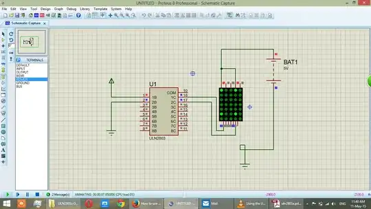
Asked
Active
Viewed 2,617 times
0
Terminator
- 119
- 2
- 7
-
It's a simulation model misbehavior and you should add pull up resistors to the outputs (for the simulation only) to correct it. Please refer to my reply http://electronics.stackexchange.com/a/98982/33841 – alexan_e May 11 '15 at 07:53
-
Yes this is the Right answer but how can i reference yours – Terminator May 19 '15 at 03:44
-
I have posted the solution as an answer – alexan_e May 19 '15 at 06:50
2 Answers
1
Try connecting pin 9 to 0V: -
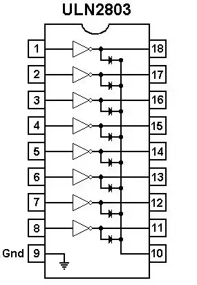
You don't appear to have a pin 9 on your model?
Current limit resistors are needed for each LED segment although this is only a simulation.
Andy aka
- 434,556
- 28
- 351
- 777
-
In Proteus devices the supply pins of IC are hidden (that is why you can't see then in the given schematic) and are automatically connected to the global power rails. – alexan_e May 11 '15 at 13:16
0
It's a simulation model misbehavior, you should add pull up resistors to the outputs (for the simulation only) to correct it.

The shown schematic is valid for simulation only, the pullup network is not needed in the real circuit.
You also have to add the current limiting series resistors for the leds of the dot display in the real circui, they are omitted in proteus to improve the simulation speed.
alexan_e
- 11,070
- 1
- 28
- 62