56

As someone starting with electronics I keep hearing, "Check the datasheet!"

Why are datasheets so important and what information can I expect to find in them? It seems like a large amount of information would come from experience and know how, not reading a long dry document the chip manufacturer publishes.

Also, is it really worth reading the entire thing?

edit
When is it OK to work at Absolute Maximum Ratings (AMR)?

stevenvh
  • 145,145
  • 21
  • 455
  • 667
  • 17
    I read datasheets in bed before I go to sleep. They're actually quite exciting and written in a clear and easy-to-understand way. Reading them makes me look forward to using all the cool features described in them :) – Stefan Paul Noack May 10 '12 at 12:58
  • 1
    It's foolish to treat man-made objects, for which documentation is available, with an empirical approach. Unless the job is to test the device (i.e. to explore the degree to which the documentation for the device is complete and true). – Kaz Jul 15 '13 at 22:57
  • 1
    You don't need to read the entire thing. Suppose a chip features analog-to-digital converters, but your project doesn't use them. Why bother reading the chapters on how to use the ADC's. – Kaz Jul 15 '13 at 22:59
  • 4
    @Kaz: For your *next* project. – Ignacio Vazquez-Abrams Aug 10 '13 at 08:17
  • @Kaz I wouldn't read the whole chapter about ADCs but I would be glad to know that there are ADCs available, how many, what sample rate, and what resolution. – user253751 Apr 05 '19 at 01:33

3 Answers3

73

Simply put: the datasheet is your complete encyclopedia on a part. A good datasheet will tell you everything you need to know about it. Use this information. Most design errors are due to (deliberately or not) overlooking certain specifications in the datasheet.


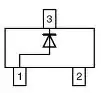
The most obvious thing the datasheet will give you the part's pinout, so that you know how to connect it. For a 144 pin controller it's obvious you can't do without that, but you may need it for a simple diode as well:

enter image description here

For relatively simple components the datasheet will mostly consist of numbers, either in tables or in graphs. One of the first tables in most datasheets will be Absolute Maximum Ratings. These are often interpreted wrongly. Not only do they mean that operating the part above the given values will damage the part, but you're also not supposed to apply these ratings in continuous operation. Absolute Maximum Ratings should only be met in exceptional situations, and never exceeded.

Next you'll have voltage and current ratings, like power supply range and consumption, and voltages and currents on specific pins. This will often be minimum and maximum values. Importance: calculation of power budget, and ascertain that you can connect part A to part B, in terms of matching voltage and required current. In particular for digital ICs threshold values are given, voltage levels where a logical zero toggles to a logical one or vice versa.

Note that values are often given as minimum/typical or typical/maximum pairs, and under the given conditions. Always work with the extremes! The following gives \$R_{DS(ON)}\$ for a BSS138 MOSFET:
enter image description here
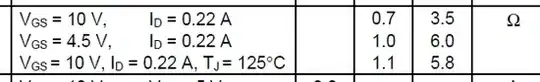
The first line says 0.7\$\Omega\$ typical, 3.5\$\Omega\$ maximum. This should be read as "Most parts will have the lower value, but don't be surprised when you see the higher on certain parts." If you design for the typical value, the ones who are closer to the maximum value may not work properly in your application! In this case you may underestimate dissipated power, so that the FET will overheat and fail long before the product's expected lifetime.
And the manufacturer almost never gives a probability curve telling you how many parts will actually have this higher value. So that means you might as well have 20% not-working products! Again, always work with maximum value.

In the spirit of "a picture's worth a thousand words" most datasheets will have a number of graphs, relating two parameters against each other. You'll often see the same types of graphs again and again for certain components, and that helps comparing them. For a (MOS)FET for instance one of the most important graphs is \$I_D\$ vs \$V_{DS}\$,

enter image description here

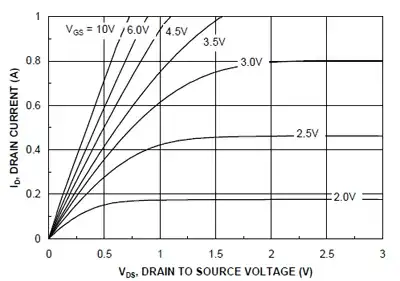
and once you get acquainted with FETs you'll recognize this specific graph immediately. (Many design engineers will first look at the pictures in a datasheet because that's the fastest way to find specific information in a sometimes long document. That's why we graduated with honors in kindergarten!)

Many datasheets will also have one or more schematics, first of all a typical application. This should get you started when you're using the part for the first time. National's analog datasheets have a great reputation of providing many application examples.
The datasheets for Linear Technology switching regulators, on the other hand, also have much application information, but more in prose, explaining theory of operation and calculations for example.
I'm just naming a few, but you'll learn that every manufacturer has his own datasheet style, and his own focus.

At the end of the datasheet you can find mechanical drawings of the part's package, and sometimes also recommended PCB footprints. The latter is often published in a document on the package, however, because it is common for all devices using that package.

The above lemmas are more or less common for most datasheets. But you can't compare the datasheet for a resistor to one of a microcontroller, of course. Especially the latter needs some getting used to. First of all, they're long! 100 pages and more are no exception. There's nothing you can do about it, they simply can perform so many functions, and everything has to be described in detail. In a microcontroller datasheet you'll see more prose than in other datasheets, because most functions can't be described just in numbers.

Microcontrollers and other digital IC datasheets also often have timing diagrams, again a picture which can tell a lot which would be difficult to explain in words.

enter image description here

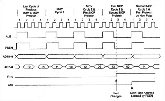
Again, they're eye-catching, so you'll find them easily.
Typical of microcontrollers is that they're part of a family, meaning there are related parts with other on-chip peripherals. To avoid having a great deal of the information identical between devices, and thus having even longer documents, most manufacturers choose to extract the common information from the datasheet and publish it in what's often called a family user manual.


You'll have to check especially the numbers when reading a datasheet. I've seen several designs fail (and I made errors myself) because the designer missed or misinterpreted some value in the datasheet. Use the information.

Before the 'Net and PCs there were databooks with collections of datasheets. Today you can find any datasheet on the manufacturer's website. If you can't find the datasheet, don't use the part!
Especially longer datasheets have an advantage in being available electronically (PDF). You can search the datasheet for certain keywords, and long datasheets like for microcontrollers have a structured table of contents with bookmarks. Again, use them!

There's a lot more to be said about datasheets, watch for more answers, but it's important to (learn how to) read them. They should give you the information you need to create a working and reliable product. If you can't find some specific information, call your distri's FAE!

stevenvh
  • 145,145
  • 21
  • 455
  • 667
  • 2
    Nice answer. +1. After one finishes meditating on this. Next step to talk about appnotes. –  Jul 15 '11 at 14:19
  • 1
    It would be good to mention Silicon Erratas also, I have only recently come across these, I'd imagine they are easily overlooked. – Jim Jul 15 '11 at 14:30
  • Even for moderately experienced electronics hobbyists, this answer provides some great reasons (refreshers) why documentation is important, necessary, and useful. Excellent work. +1 – JYelton Jul 15 '11 at 15:28
  • 1
    Great answer! I love it when the experts boil their years of experience into a comprehensive answer that even beginners can understand, it saves us form making beginner's mistakes! – Faken Jul 16 '11 at 05:17
  • 1
    One thing to note: even datasheets can contain errors, which are *sometimes* corrected in erratas. (Which is the wrong place IMO). Check for instance http://electronics.stackexchange.com/questions/18783/multiple-pulses-from-single-button-press – Wouter van Ooijen Sep 13 '11 at 21:01
  • Timing diagrams can be nice, but one thing that's very important to note is that they are usually *not drawn to scale*. Further, the fact that an edge is drawn before another edge does not imply a chronological relationship between the two unless one is explicitly indicated (though diagrams will often show a repeated sequence of events, with different timing relationships shown on each; a timing relationship shown on one sequence will generally apply to all). – supercat May 11 '12 at 15:26
  • are you working for national semiconductor ? – Standard Sandun May 28 '12 at 20:06
  • "call your distri's FAE" < what you mean by FAE? is that bad word ? – Standard Sandun May 28 '12 at 20:12
  • 2
    @sandun - FAE = Field Application Engineer. They're employed by the distributor to deliver free support to professional engineers. Good FAE support is high-valued, and may influence the choice for a specific distributor. – stevenvh May 29 '12 at 05:03
11

"When is it OK to work at Absolute Maximum Ratings (AMR)?"

Never, unless they're the same as Recommended Operation Conditions. This is a discussion I'm having sometimes. Tony says

"the device will not fail if you stay within the Absolute Maximum rating or even if you happen to meet the Absolute Maximum Rating"

That's a bad attitude! You should stay away from AMR.

Let's pick some random device. Recommended Operating Conditions say \$V_{CC}\$ should be between 1.65V and 5.5V. Limiting values (In accordance with the Absolute Maximum Rating System (IEC 60134)) say \$V_{CC}\$ should not exceed 6.5V.

Some people seem to find this 6.5V OK, or suggest to keep some margin from it (lots of hand waving). Indeed, and that margin is given: 5.5V. That already gives you some margin, because it actually refers to 5V\$\pm\$10%, so if you're working with a normal 5V\$\pm\$5% you're more than safe.

Why isn't 6V OK? Because every parameter is specified for Recommended Operating Conditions. Once you go beyond the 5.5V you can't rely on anything anymore. In the worst case the device may show unpredictable behavior (no, indeed, it won't fail). It can be a simple thing like supply current. That's specified at 200\$\mu\$A maximum. Don't go complaining at NXP if it's higher at 6V! An EEPROM may be specified at 1 000 000 erase/write cycles. Well, that's under Recommended Operating Conditions. If you go beyond that, even when you stay away from Absolute Maximum Ratings, the number may be lower.

Stick to Recommended Operating Conditions. They already include some margin.

Blair Fonville
  • 3,837
  • 4
  • 19
  • 45
stevenvh
  • 145,145
  • 21
  • 455
  • 667
  • If a part gives an Absolute Maximum Rating of 70C for a storage temperature, would there be anything in a typical data sheet that would indicate whether one could leave the part at 69.999C for five years without degradation, or what the maximum storage temperature without degradation would be? – supercat May 10 '12 at 16:05
  • @supercat - Values above AMR mean almost certainly damage to the device, but that doesn't mean that there's no degradation if you stay below it, even at 60°C. I haven't seen this in datasheets, but the **packaging** often indicates a "use before" date. I've often seen it for vacuum packages ICs on trays. – stevenvh May 11 '12 at 06:05
  • 3
    Values above AMR don't mean "almost certain damage", since there are many devices in service which have been operated outside AMR for years. The "use before" dates often relate to the fact that the pins on unused parts will eventually oxidize (the packaging keep oxygen out forever). Once parts are on a board, pin oxidation is generally not a concern. In any case, if an AMR storage temperature of 70.0C doen't mean it's safe to keep the part installed but not powered up for years at 69.99C, what does it mean? – supercat May 11 '12 at 15:22
9

"When is it OK to work at Absolute Maximum Ratings (AMR)?"

Almost never. If you want your circuit to work as expected (as the datasheet says it should), design to the normal operating conditions and forget about the AMR.

The AMR are the limits that won't immediately cause permanent damage to the device, so they can be relevant if your device might be subjected to a short trip beyond the NOC but within the AMR, during which it is not required to work normally, but after which it will return to the NOC and is expected to work normally again.

Think of a drop from the table, a lightning strike nearby, a nuclear event, an electrostatic discharge, etc. But, again, the device is not required to work normally while any condition exceeds the NOC, but it should operate normally again once the (short!) NOC-exceeding trip is over (maybe only after a reset, power cycle, etc.)

In short: NOC are the (normal) operating conditions, AMR are the (short-stay only) survival conditions. Don't expect normal working inside the AMR but outside the NOC, that is NOT what the AMR are for.

Wouter van Ooijen
  • 48,407
  • 1
  • 63
  • 136
  • Agreed, but it's worse. Say a 5V device has AMR 7V, and has specs under the condition that power is between 4.5V and 5.5V, even then you can't rely on it anymore at 6V, even if that's not even near AMR. You won't get permanent damage, but it won't comply with specs. – stevenvh May 28 '12 at 19:05
  • How is that 'worse' than what I describe? - Oh I see, it is the interpretation of the word 'work'? I'll edit. – Wouter van Ooijen May 28 '12 at 19:09
  • No, I meant you don't have to look just at AMR. It's also the specified ranges as condition for normal use. – stevenvh May 28 '12 at 19:13
  • @steve I don't get what you mean. AMR are the (short term) survival limits. Nothing more, but certainly nothing less, so they are relevant in some very very limited cases. – Wouter van Ooijen May 28 '12 at 19:16
  • In the example I used people could think everything is OK as long as Vcc < 7V. But for instance supply current can specified at 1mA max for Vcc between 4.5V and 5.5V. At 6V it may be more, but the 4.5V-5.5V condition is often overlooked because it's mentioned at the top of the table, not with each item. – stevenvh May 28 '12 at 19:21
  • Everything *is* OK with Vcc < 7V, provided that a) this is for a short period only, and b) the device is not expected to do anything but surviving (this implies that it can behave strange, draw excess supply current, oscillate in funny ways, maybe erase its firmware, etc) – Wouter van Ooijen May 28 '12 at 19:28
  • Seems we agree! :-) – stevenvh May 28 '12 at 19:29
  • I'd say the NOC specifications only are valid when operated within the NOC. When 6V is applied to the device, such as an opamp or something, it 'may' produce more noise, have less gain, have more input offset, may not be R-R or whatever weird things. Operating out of the NOC is a path into unknown. This doesn't even necessarily have to extend beyond the AMR; I see AMR more as the set of parameters that can induce permanent failures. – Hans May 28 '12 at 20:57
  • @Hans: is there anything I wrote you disagree with?? – Wouter van Ooijen May 28 '12 at 21:16