6

I'm working on a project to make a wristwatch similar to this one:enter image description here

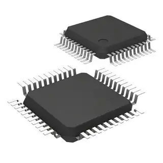
Now I have the ability to make flexible PCBs since I accidentally bought some crazy thin copper clad. I obviously want to use SMD LEDs since they're pretty small. What type of \$\mu \$C package should I look for that will be nice and thin but still DIY solderable (the only one I know of is QFP but I'm not sure I could solder one of those)?

Lastly, are there any other common pitfalls when making flexible circuits? I can imagine people bending the PCB all over and accidentally touching traces etc.

EDIT I'm thinking about not making the circuit flexible, but storing components inside each little compartment of the watchband. Then I just need flex cables to go between the parts of the watchband for communication and power. Probably only need a few traces... this would lessen (almost eliminate) the stress on any solder joints and place it only on the material the communication traces are put on. Whether I decide to make that out of polyimide or just my thin FR4 is yet to be determined. Does this seem reasonable?

Thanks

NickHalden
  • 4,167
  • 3
  • 31
  • 40
  • That watch doesn't look like it has any flexible electronics; just a case and band designed to match. – Kevin Reid Jul 13 '11 at 04:03
  • One thing to be aware of is that many types of ceramic capacitor don't like to be flexed. – Thomas O Jul 13 '11 at 06:30
  • Is your copper clad actually a piece of [flex circuit](http://en.wikipedia.org/wiki/Flexible_electronics), or is it just some really thin FR4? The pitfall with the latter is that the copper clad will get hairline cracks and develop strange bugs. You should probably research flex circuits more thoroughly and return with a more focused question. There are volumes of information about flex circuits - far more than can be expressed in a single answer here. – Kevin Vermeer Jul 13 '11 at 15:29
  • @Kevin It is in fact just really thin FR4, but I don't know that it's a problem. As you can see from the picture (and kind of Kevin Reid's comment) it doesn't flex a whole lot. What kind of timeframe are we talking to develop cracks in your experience? This is just a hobby project so I don't really care if it only works for a week or two. – NickHalden Jul 13 '11 at 15:41
  • @JGord, if you are wearing it and flexing it regularly, I would expect less then a day. – Kortuk Aug 04 '11 at 11:13

3 Answers3

4

To start with your last question: this really looks like the weakest link in your project. Flexible PCBs are not made to work under mechanical stress.

open-heart camera

They're often in a fixed position and the parts which can become under mechanical stress (like user controls) are always fixed, either with a screw, or with a molten piece of plastic. In particular the parts of the flex-PCB which have components soldered on them should not flex, as creepage may cause solder connections to fail in time.

enter image description here

This is more of a mechanical than electronic problem, but I would make sure that there's always another mechanical part which will take the stress when flexing. It could also shield the PCB from touching.

As for the package, it's true that QFN is becoming more popular, but most microcontrollers are still available in LQFP/TQFP (Low Profile Quad Flat Package/Thin Quad Flat Package), with pitches from 0.5mm over 0.65mm to 0.8mm (wider pitch usually on devices with less pins).

LQFP44

The last one should be rather easy to solder, and even 0.5mm is doable with a fine tip soldering iron and a steady hand (ask your dentist! :-)).
It's hard to select a microcontroller purely by package, so maybe you could give us some details, like number of I/Os.

stevenvh
  • 145,145
  • 21
  • 455
  • 667
  • Requirements for the MCU are pretty damn slim. It needs to have a timer interrupt, and preferably a hardware implemented serial interface (either I2C or SPI) so that I can easily interface with an LED driver chip. Also, see my edit. Thanks – NickHalden Aug 04 '11 at 15:00
  • What do you need a fine pitch iron for to solder 0.5mm leads? In fact i'd never recommend that. I just use a tip the size of the entire side of the chip. With proper use of flux and the correct solder you can solder the entire chip in seconds. – Mark Aug 04 '11 at 15:29
  • @Mark - If I do that I often get shorts between pins. To everyone his own method, shall we say? – stevenvh Aug 04 '11 at 15:43
  • I think flex-circuits printed on decent substrate can stand repeated bending so long as the radius is 20-50x the thickness (more is better obviously) of the PCB. This is for single-sided only, however, and traces parallel with the curve (no components). – Nick T Aug 05 '11 at 00:57
2

Seeed Studio sell a flexible Arduino which could make a good base to work from: http://www.robotshop.com/seeedstudio-seeeduino-film.html

http://www.seeedstudio.com/blog/2010/06/29/seeeduino-film-maybe-the-first-arduino-board-on-fpc/

They seem to be using an AVR QFP.

Toby Jaffey
  • 28,796
  • 19
  • 96
  • 150
  • Interesting... I might try to make something similar, but without all the charging circuitry and extra junk I don't need – NickHalden Aug 04 '11 at 15:06
1

I recommend a microcontroller in a TSSOP package. TSSOPs are pretty small, but still possible to solder by hand, even if you don't feel comfortable with a QFN.

Try the PIC16F1823.

Rocketmagnet
  • 26,933
  • 17
  • 92
  • 177
  • Any reason for that particular PIC? Now it looks like the only reason is the package, and that's not enough IMO. – stevenvh Aug 04 '11 at 10:15
  • 1
    Correct, the only reason is the package. While this is not a great reason to choose a microcontroller, sometimes we are forced into a certain choice by mechanical constraints. In this case, he needs a very small MCU which is easier to solder than a QFN package, but still small enough to fit in a watch, while at the same time having enough pins to handle all the LEDs. This basically forces the choice of TSSOP package. – Rocketmagnet Aug 04 '11 at 12:25
  • 1
    Also, the MCU has the features he needs for a watch: Suitable pin count, ultra low power, works down to 1.8v. It's also FLASH, rather than OTP, so it's good for prototyping. – Rocketmagnet Aug 04 '11 at 12:27
  • Lastly, a TSSOP package is very slightly more flexible than a QFN. – Rocketmagnet Aug 04 '11 at 12:27
  • I wouldn't count on flexibility of QFP pins. If they bend it means the solder is also under stress, and that will cause **creepage**, and ultimately breaking, as I mentioned in my answer. – stevenvh Aug 04 '11 at 12:32
  • Yup, which is why TSSOP is clearly better for this project. – Rocketmagnet Aug 04 '11 at 13:22
  • I misquoted you saying QFP instead of TSSOP, but the problem is the same: solder connections under stress suffer from creepage, which eventually leads to broken connections. – stevenvh Aug 04 '11 at 13:30
  • 1
    I agree. However, all components can cope with some flexing, and a TSSOP can cope with more flexing than a QFN can. – Rocketmagnet Aug 04 '11 at 13:46
  • 1
    @RocketMagnet, you really have put the only part I see as an answer in comments. In your answer you should probably edit more of your reasons. Right now it is a very short comment. – Kortuk Aug 05 '11 at 14:12