4

It's awkward, but I have accidentally put STM32 nucleo on the washing machine. Though full of soft clothes, the machine managed to tear the ST-link part of the nucleo off:

image description

This means the nucleo is probably still working but I need to reconnect it to the ST-Link part.

My question is, can I connect some of the pins on these two parts to make the whole work again?

Tomáš Zato
  • 1,044
  • 4
  • 21
  • 40
  • 2
    Buy a new one, they aren't expensive. – Leon Heller Apr 30 '15 at 19:51
  • 1
    @LeonHeller For me everything is expensive just now and will be until I get a summer job. – Tomáš Zato Apr 30 '15 at 20:25
  • 1
    Of course you can do it! ST-Link can be used as a stand-alone programmer, that's why the board was designed to be separated in the first place. Refer to the datasheet of your uC, identify the pins you need and connect them to SWD with jumper wires. – v.m. May 01 '15 at 18:16
  • @v.m. well I read the datasheet and didn't find anything mentioning how to reconnect it. – Tomáš Zato May 01 '15 at 19:20
  • 1
    Nucleo boards are manufactured with different MCUs. What device does your board use? The pins you need are SWDIO, SWCLK, nRST, VCC and GND. – v.m. May 01 '15 at 19:43
  • @v.m. Could you please draw something on the board image to picture what I should be connecting? I cannot figure it out :( – Tomáš Zato May 13 '15 at 23:58
  • 1
    I'll try to help, but I need to know which nucleo board you're using. As I said - there are different boards with different micros and the pinout might differ as well. What is the marking on the main uC? – v.m. May 14 '15 at 17:26
  • Sorry, I totally forgot! My nucleo is marked NUCLEO-F411RE. Here's [the main board](http://i.stack.imgur.com/7JGvn.png) and here's [the STLink](http://i.stack.imgur.com/Fe04M.png). – Tomáš Zato May 14 '15 at 20:33
  • @v.m. Actually the SWD signals are always PA13 and PA14. One would not contact the bare chip but rather the labeled headers. – Chris Stratton Sep 22 '19 at 13:46

4 Answers4

6

Here is what worked for me:

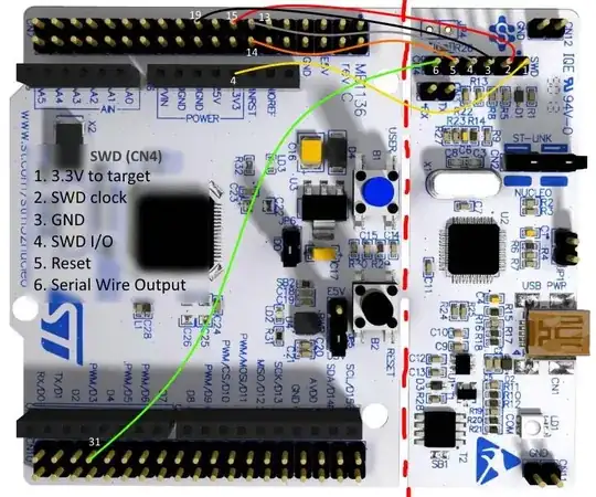
If the stlink is actually broken off, the nucleo should be powered by the stlink, the yellow wire going from the the upper pin of JP1 on the stlink to pin 16 of the nucleo supplies the 3.3V (the other yellow wire going from nucleo pin 4 to swd/cn4 pin 1 is used by the stlink to measure the voltage).

As with measuring the voltage: also make sure that R9 on the stlink exists, on mine it was empty, I had to solder a 4K7 resistor, before that, the voltage was read as 0V by the stlink and open OCD was issuing a warning message "target voltage may be too low for reliable debugging”

The jumper on the nucleo JP5 should be removed as to deconnect from the output of the onboard regulator.

If you are programming another nucleo where the stlink is NOT broken off, on the other nucleo stlink the 0 ohm resistor on SB12 should be removed as to deconnect the reset line going from the NOT broken off stlink to the nucleo, otherwise the connected stlink, when not powered will hold the reset line.

Optional connections (35, 37) to RX and TX require connecting the bridges SB62 and SB63 under the nucleo board, this allows to use the virtual comm port of the stlink wire connections schematic

jluu
  • 333
  • 3
  • 5
5

Here is a STM32 Nucleo (64 pins) schematics. In archive you will find PDF schematic as well.

I have not tried it myself, but it seems that you should be able to connect ST-Link like this:

wiring ST-Link to target board

Anton Kedrov
  • 567
  • 3
  • 9
1

I found the offical usage:

6.3.4 Using ST-LINK/V2-1 to program and debug an external STM32 application It is very easy to use the ST-LINK/V2-1 to program the STM32 on an external application. Simply remove the two jumpers from CN4, as shown in Figure 10 and connect the application to the CN6 debug connector according to Table 5. Note: SB111 NRST (target STM32 RESET) must be OFF when CN6 pin 5 is used in an external application.

Table 5. Debug connector CN6 (SWD) Pin CN6 Designation

1 VDD_TARGET VDD from application
2 SWCLK SWD clock
3 GND ground
4 SWDIO SWD data input/output
5 NRST RESET of target STM32
6 SWO Reserved 

pdf: http://www.st.com/content/ccc/resource/technical/document/user_manual/group0/26/49/90/2e/33/0d/4a/da/DM00244518/files/DM00244518.pdf/jcr:content/translations/en.DM00244518.pdf

Lingreate
  • 11
  • 1
  • CN6 is on the STLink board which has come away from the main processor board in the wash, so this wouldn't work. These instructions are for programming an intact Nucleo via an external STLink and not the USB version built into the snap-off board. – sergeantKK May 23 '19 at 15:40
  • @sergeantKK that's incorrect: these instructions are for programming an _external board_ from the ST-Link chip that's connected to the Nucleo (and can be snapped off, as the OP did). These instructions are correct, just incomplete for the OP since they don't say which pins on the Nucleo itself the CN6 pins need to go to – villapx Oct 08 '19 at 18:08
-1

I think NO.

I see traces on all three of the connecting bridges, I count 11 in total. Some of them quickly lead to through-holes, but not all, and even those that do will be difficult to solder due to that nice white finish. (And that assumes that it is just a two layer board. There could be traces in hidden layers...)

Take Leon's advice. These boards (and a lot of similar boards, from ST and others) are dirt cheap for what they offer.

But if your time is cheap why not identifiy the traces, find suitable pickup-points (or create them by scrapping the white layer off), and connect the two boards with wires. You've nothing to lose but your time.

Wouter van Ooijen
  • 48,407
  • 1
  • 63
  • 136