1

Currently I am trying to work with a photodiode(SFH 203) that is supposed to detect very small amount of light. Using the digital of an arduino the photodiode cannot turn the pin to 1 due to the low level of light. If I measure light with an anlaog pin I receive a value arnd 25-30.

Is there any way to bring the digital value to turn 1 using a small amount of light?

enter image description here

Sathees
  • 125
  • 1
  • 3
  • 11
  • Could you provide a link to the datasheet, so we don't have to look for it? :) – Dzarda Apr 30 '15 at 11:58
  • Do u mean the datasheet for the photodiode? – Sathees Apr 30 '15 at 12:04
  • http://www.osram-os.com/Graphics/XPic2/00101659_0.pdf/SFH%20203%20P,%20SFH%20203PFA,%20Lead%20(Pb)%20Free%20Product%20-%20RoHS%20Compliant.pdf – Sathees Apr 30 '15 at 12:04
  • 3
    You show the photodiode forward biased- Usually a PIN photodiode is reverse-biased. Not sure why you have an LED in series. If you don't care about speed you could reverse bias it with a large load resistor to ground and use a comparator to feed the digital pin. Ideally, the reverse bias voltage would be higher than 5V, the datasheet gives a max value of 20V, so 12V might be OK if it's available. – John D Apr 30 '15 at 12:15

4 Answers4

3

From what I know, photodiodes work "backwards". That is, they create a current flow from the cathode to the anode, so in your schematic \$PD\$ is likely the other way around. This way, there's no light detection going on, I guess current will flow through the circuit at all times.

schematic

simulate this circuit – Schematic created using CircuitLab

The above schematic is my attempt at minimizing what's required for digitizing the PD output. It relies on the roughly-100 current gain (Beta) of the \$Q_1\$ transistor. \$10\mu A\$ should be enough to cause \$1mA\$ flowing through the collector-emitter junction. \$R_1\$ is simply a pull-up that says, that in dark conditions, the output will be HIGH. \$Q_1\$ then pulls it low-ish, when \$PD\$ gets illuminated enough.

To fine-tune the sensitivity threshold, you can try adjusting \$R_1\$ (or potentially replacing it with a potentiometer.)

Feel free to point out any mistakes I've made.

Dzarda
  • 3,020
  • 1
  • 16
  • 23
1

The datasheet shows the photodiode's sensitivity as 9.5 uA per 1000 Lux.

Now I don't know what counts as "low light" to you, but let's try 10 Lux as a reasonable switching lu]evel - at that point, the photodiode will produce 95nA. Not very much ... how does it compare with the dark current? well that is specified as <10nA so 95nA is clearly above the dark current.

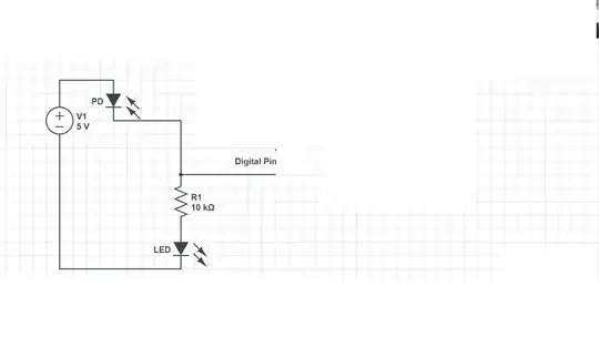
So we want to set the Arduino input to 1 (i.e. > 2.5V) with a current of 95nA. Neglecting the LED for the moment (there's no way it'll light up anyway) you can simply do this by replacing R1 with R = 2.5/95e-9 = 27 Megohms or so.

If the Arduino input pin leakage current is much greater than 10nA this won't be accurate, and if it's greater that 100nA it may not work at all, or the switching level may be something greatly different from 10 Lux, but you haven't posted the relevant datasheet so I can't check that.

(and as John D points out, connect the photodiode right way round!)

  • Thx! I just changed the resitor to 1Megaohm and the digital pin turns 1 providing light (20 lux); however even without light its analog value is at 400....well is there a pd u can recommend for its high sensitivity for white led light? – Sathees Apr 30 '15 at 14:18
  • "analog value is 400" out of what? 1000? 4000? 65536? That's the dark current + Arduino pin leakage current. As for a better pd, now you know how to read the spec sheets so maybe you can find one yourself. –  Apr 30 '15 at 16:22
1

The SFH203, from looking at it's datasheet, has a λS max sensitivity range from 850-900nm, which is the near-infrared range. It is less sensitive (up to 10% of max) at the visible light frequencies. There is a sensitivity chart included. So if you are using a blue LED for light, this can explain all of the loss in sensitivity. Use an 875nm near-IR LED and it will be much more sensitive.

Or if you are already using an 875nm LED and it's still not sensitive enough, then you'll have to use an op-amp such as one of these to increase the gain.

In your circuit, the 10k resistor would limit the current in the (regular) LED to a value so small, it would probably not even emit light. Also, photodiodes generate a tiny reverse current when emitted to light, not forward conductance. Take a look at this post for another way to implement the photodiode.

rdtsc
  • 15,913
  • 4
  • 30
  • 67
  • thx for the link. Do u think that an op amp would increase the sensity of the PD, as described in the link? – Sathees Apr 30 '15 at 14:12
  • Definitely. An op-amp's gain is typically set with two resistors. Depending on the performance of the chosen op-amp, gain can be 100,000x or more. (But at such large gains, noise and interference become issues.) – rdtsc May 02 '15 at 15:53
0

As noted in the datasheet, the SFH 203 can only deliver around 10 microamperes of current.

Your LED alone will draw more current than that.

The Arduino input should be happy with the 10µA. Remove your LED and R1.

If it still doesn't work, you may need to buffer the photodiode with a transistor to increase the current.

JRE
  • 67,678
  • 8
  • 104
  • 179