3

can someone explain me how to connect and use varicap diodes?

Please consider that I am a novice, so would be ok to use a clear and an exhaustive language/terms. Thank you.

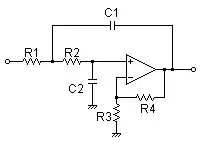
I often see these schematics:

varicap connections

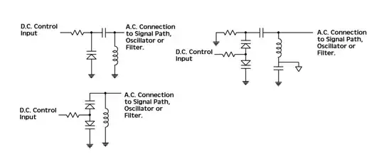
The first thing is: from what I heard, a resistor between the V tuning and the varicap is needed to remove the DC signal, or is also possible to insert an inductor or a capacitor; which component is better to choose and of what value? And if I avoid to insert the resistor/inductor/capacitor in what "risks" I can fall?

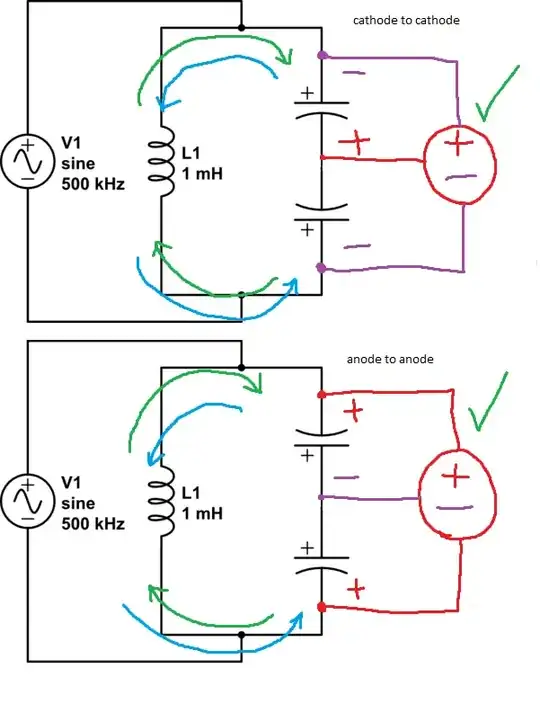
The schematic also shows that is possible to connect these varicap in a back-to-back configuration (anode to anode): in this way the total capacitance is the half of one diode. But I have a doubt: in this schematic (bottom left image) the varicaps are DC shorted by the inductor, right? Why aren't DC isolated from the circuit? So, is better to prefer the schematic in the top right image? Seems that here, the capacitors are used to isolate the varicaps. But from what I can see, in a lot of schematics, varicaps aren't isolated from the circuit. Is not very clear to me.

Anyway, in the following image:

varicap connections 2

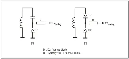
I can also see that is possible to connect them with the cathode in common: which configuration is better?

Can someone explain me which connection is preferable and why (anode to anode, cathode to cathode or just with a capacitor in series - and how to choose the series capacitor to avoid to reduce the capacitance range of the varicap), how to properly isolate them from the DC signal and from the circuit? Would be also nice to see some practical/didactic schematic (with component value) to exactly show and understand howa circuit can operate.

Many thanks.

Mister D
  • 205
  • 1
  • 5
  • 13

3 Answers3

5

Here's what I know;

Image (a) - That capacitor above the varicap isolates the tuned circuit from the DC tuning voltage, but still allows the capacitance of the varicap to contribute to frequency modulation since it's still a part of the tuned circuit.

Image (b) - If you replace the capacitor above it with another varicap, as shown on the right, not only are you able to tune both at once with the same tuning voltage, but inherently the tuning voltage is isolated from the tuned circuit, without the need to add the big capacitor to block it, and thus you only have the capacitance of those varicaps in combination to add to your circuit.


If you want a circuit to be tuned to \$ f \$ constant frequency (100kHz);

$$f = {1\over 2\pi \sqrt{LC}}$$

$$100000 = {1\over 2\pi \sqrt{(0.001H)C}}$$

$$C = 0.0000000025F$$

$$C = 2.5nF$$

schematic

simulate this circuit – Schematic created using CircuitLab


If you want to get your circuit to tune within a range over or below a certain limit, use the series cap and the varicap;

$$f = {1\over 2\pi \sqrt{L(C + \Delta C)}}$$

$$f = {1\over 2\pi \sqrt{(0.001H)(0.000000025F + 0F)}}$$

$$f = 100000Hz$$

schematic

simulate this circuit

For example, I want to tune a circuit that normally operates at 100kHz from 100-120kHz. I can use the big capacitor to define the 'start point' of 100kHz and also block my tuning voltage. Then the varicap's additional capacitance in series lets me maneuver from 100 to 105 to 110 to 115 to 120kHz.

$$f = {1\over 2\pi \sqrt{L(C + \Delta C)}}$$

$$f = {1\over 2\pi \sqrt{(0.001H)(0.000000025F + 0.0000000175F)}}$$

$$f = 120000Hz$$

schematic

simulate this circuit


If you want to get your circuit to tune over the entire range, use the back-to-back varicaps;

BEWARE: Two back to back varicaps (V1 + V2) gives you \$1\over2\$ capacitance, so just V1.

$$f = {1\over 2\pi \sqrt{L (\Delta C)}}$$

$$f = {1\over 2\pi \sqrt{(0.001H) (0.0000000001F)}}$$

$$f = 500000Hz$$

schematic

simulate this circuit

In this example, I want to tune a circuit from scratch to operate at 0-500kHz. In order to get that full range of frequencies, I use two varicaps back-to-back in order to avoid having to set a 'start point' frequency, and then I use the DC voltage to change both of their values at once.

$$f = {1\over 2\pi \sqrt{L (\Delta C)}}$$

$$f = {1\over 2\pi \sqrt{(0.001H) (0F)}}$$

$$f = 0Hz$$

schematic

simulate this circuit

Also, this allows you to work with higher voltage waves, just in case the AC signal is enough to reverse bias your varicap and mess everything up.


Remember, tuned circuits aren't meant to operate with DC, they operate with AC, either V+ to V-, or V+ to 0, or 0 to V-.


Also; in regards to the resistor or inductor on the biasing input, you'll need something that impedes it enough to not affect your tuned circuit, but doesn't impede it so much that you drop voltage all the way to 0V and basically do nothing. It all depends on how fast you want your circuit to go. At lower frequencies you can get away with just letting the caps do their thing. At higher frequencies, a high-value resistor or inductor will do.


Prefer the (a) connection when you want to have a heavier effect on a frequency, or when you must operate above a certain frequency by a certain amount with your bias input.

Prefer the (b) connection when you must operate within the entire frequency range with your bias input.


The DC and AC never interact to any reasonable level.

enter image description here

ARMATAV
  • 603
  • 7
  • 19
  • Thank you, you have been very clear and exhaustive! But I have still some doubts about the "anode to anode" and "cathode to cathode". If on the tank circuit I have the V+, I have to choose "anode to anode", and so the cathodes will block the DC from the rest of the circuit. And I will need a negative bias input to drive the varicaps, as cuddlyable3 stated. In this configuration, to feed the varicaps, so I would need another dedicated circuit which is able to give me a negative DC? But this negative DC would be conducted across the anodes of the varicaps. This point is not very clear for me. – Mister D Apr 28 '15 at 17:52
  • Here, I'll clear things up. The tank circuit is AC, and must go from V+ to V-, or to 0. It's unnecessary to have a negative DC supply, you must just switch the position of the ground to the other side of your varicaps, so it "thinks" it's getting negative bias. Putting the varicaps in cathode-to-cathode or anode-to-anode works since the tank circuit is AC, and therefore it will bias one of the varicaps properly, and bias the other one improperly. That's why you only get half the capacitance. Both varicaps do not block the AC only one does. – ARMATAV Apr 28 '15 at 18:07
  • The DC biasing signal does not carry significant current, and so in any case, it will not be able to affect your circuit within reason. Anode-to-anode blocks the DC if you put the DC ground on the outside of the varicaps, cathode-to-cathode blocks the DC if you put the DC ground on the inside of the varicaps. – ARMATAV Apr 28 '15 at 18:12
  • Here, I drew this for you. Notice how the AC and DC signal never interact with each other in both cases. The varicaps, and, if you use one, the bias resistor, never let them touch. http://i.stack.imgur.com/pswgO.png – ARMATAV Apr 28 '15 at 18:21
  • Thank you again: now is more clear how everything work! However (and probably this is the last interrogative): what about if I drive the varicaps in "anode to anode" configuration, using a triangle wave or a sawtooth tuning voltage? I will need a triangle/sawtooth wave which go (example) from 0 to -V max (the needed max voltage for the varicap)? – Mister D Apr 28 '15 at 18:45
  • Yes, that is correct. Remember; the voltage is inversely proportional to the capacitance, however. As you saw in my examples, if you increase the voltage, you "squash" the capacitor plates together, making the capacitance smaller. That said, you don't need a wave. If you want your capacitors to be at max capacitance, don't apply bias voltage -V. If you want them to be at minimum capacitance, apply CONSTANT bias voltage -Vmax. If you want them to be at half capacitance, appply CONSTANT half -Vmax. A wave input will fluctuate the tuning frequency. A constant input will keep it constant. – ARMATAV Apr 28 '15 at 18:52
  • I was talking about a triangle/sawtooth wave since I've seen that varicaps are also used to make vco and sweep/wideband oscillator, so I was thinking about the fact that applying a sawtooth to varicaps, this will cause the tank circuit will continuously oscillate/drift on a given range of frequencies. – Mister D Apr 28 '15 at 19:01
  • Oh, I gotcha. Yes, you're right. If you sweep through 0 to -Vmax it will cause the tank circuit to change it's resonant frequency accordingly. However, this will not, provided you are using the correct resistors and such things (you can experimentally figure this value out by yourself), affect the AC waveform. They are isolated. It will simply tune the circuit up and down in accordance with your waveform. So yes, if you want to tune it with a sawtooth, go ahead, it will need to go from 0-Vmax if you want the full range. – ARMATAV Apr 28 '15 at 19:10
  • You're welcome, have fun with the information! – ARMATAV Apr 28 '15 at 19:14
  • 1
    Unfortunately, since I don't have enough reputation points, I cannot give you a "+1" vote to your answer, I'm very sorry! – Mister D Apr 28 '15 at 19:15
  • It's alright, I don't care about the points. I just like typing out the stuff I know so it becomes permanently ingrained in my mind. – ARMATAV Apr 28 '15 at 19:16
  • I have posted another question to go to the next step, to put into practice what I'm learning. However, in my new question, I posted a schematic (on the bottom) which infringes what you explained me. If you have some time can you take a look to that schematic? Now I am a little bit confused :-) – Mister D Apr 28 '15 at 21:34
0

In the bottom left image, the DC is blocked by the blocking capacitor which has no identification. It is typically selected to be a value that has essentially no effect on the tuned circuit.

On the right hand schematic, both diodes are reverse biased, so again, no DC is flowing in the inductor. Generally, for creating tuning circuits the figure (b) is preferred, as strong, nearby signals will cancel out on the pair of varactors.

Usually, the bias resistor for the varactors is up in the megohms, not 10-48K as indicated; at least in all of the RF circuits I have played with.

And, as for capacitance, you need to look at the manufacturers sheet for your various diodes to see how much capacitance can be generated by what bias voltage range. The typical range for varactor tuning diodes is about 1 to about 50 pF maximum. It is generally easier to put several stacks (as in b) in parallel to develop higher capacitance.

R Drast
  • 4,145
  • 15
  • 18
  • There used to be varicaps for AM radio, in the 200pf region. With the decline of AM radio, they seem to be no longer made, and 50pf (or 30pf or less) are what you get now. –  Apr 28 '15 at 16:55
  • Thank you. I've seen many circuits which include a bias resistor with a common value between 10k and 47k, but you're claiming that this resistor should be up in the megohms value; there is some formula/value to calculate a proper bias resistor? Some schematics, instead, includes a bias capacitor of 100nF value: which solution is better? – Mister D Apr 28 '15 at 17:17
  • You must sacrifice Q of the circuit when using a resistor, and you must sacrifice smoothness of the signal when using an inductor. You should be able to experimentally define the values depending on your circuit and needs. – ARMATAV Apr 28 '15 at 17:58
0

>"in (bottom left image) the varicaps are DC shorted by the inductor, right?" The inductor resonates with the capacitance of two varicaps in series, i.e. half the capacitance of one varicap. Note that the D.C. control input must be negative to keep the varicaps reverse biased. For a positive D.C. control input, connect the pair of varicaps cathode to cathode instead.

>"is better to prefer the schematic in the top right image?" No, assuming the two unlabelled capacitors are large compared to the varicaps this circuit works just the same. Be aware of the formula for the capacitance of two capacitors in series: Ctotal = C1 x C2 / (C1 + C2).

cuddlyable3
  • 468
  • 2
  • 10
  • Let's suppose that in a given circuit/tank circuit/oscillator I have to choose the "anode to anode", when on the inductor I have the positive voltage: I guess that in this way (the cathode is on the V+) the varicap will act as any other diode, refusing to conduct the current from the circuit. So, in this given configuration (anode to anode), I have to rely on a different circuit to achieve a negative D.C. control? I say: if I put the cathodes on the V+, I will need another power source (negative D.C.) to drive them, right? – Mister D Apr 28 '15 at 17:24
  • You don't need another power source, you simply change where the ground goes for your circuit. For cathode-to-cathode; V+ goes in the middle, V- goes on the ends. For anode-to-anode; V+ goes on the ends, V- goes in the middle. You cannot use the power source that drives your LC circuit to bias the varicaps. – ARMATAV Apr 28 '15 at 17:54