I am trying to build a micro controller system where I input music from a phone/tablet and control the volume using a hardware keypad and do other stuff with the audio. I am trying to understand how to convert the +/- 2.5 V audio signal from phone to 0-5V for micro controller input. Thanks
Asked
Active
Viewed 1,619 times
0
-
Add an offset or use a clamper. – nidhin Apr 23 '15 at 08:50
2 Answers
2
This circuit, a non-inverting summing amplifier, can be used for your purpose.
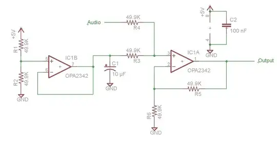
The left op-amp is a 2.5v voltage reference (derived from your 5v supply), and the right op-amp is the summing amp. With the values shown, it takes the ±2.5v Audio input and adds it to the 2.5v offset, resulting in a 0-5v output.
If R3 = R4, then Output = Gain * (Audio + Ref) / 2
Gain = (R5 / R4) + 1 = (49.9K/49.9K) + 1 = 2
so Output = 2 * (Audio + Ref) / 2 = Audio + Ref.
tcrosley
- 47,708
- 5
- 97
- 161
-
If you replace R3 with a 100k to 5V and a 100k to 0V you can use one op-amp (providing the 5V is fairly clean). – Andy aka Apr 23 '15 at 09:38
2
If your input signal is within the constraints of +/- 2.5V then it just needs to be lifted from an average voltage of 0V to an average voltage of +2.5 volts. In doing so, the output becomes constrained to a range of 0 to +5V. If the input is generally audio/music then you can use a capacitor and voltage divider like so: -
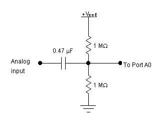
If Vref is 5V, the average dc output level is 2.5 volts because the two resistors are equal value. There will be a low frequency cut-off point and, for the circuit above, this will be: -
\$\dfrac{1}{2\pi (\frac{R}{2})C}\$ = 0.677 Hz for the values shown.
You may choose to lower the two resistors to 100k and then the low frequency cut-off will be 6.77 Hz. There are many combinations of C and R that can be found to produce a cut-off below 20 Hz.
For instance, if the level-shifted output were to feed a PIC, you'd want to keep the resistor values no-more than 20k. With two 20k resistors and a 1uF capacitor the cut-off will be 15.9 Hz.
You might also consider adding an RC low pass filter after the circuit above to prevent aliasing in your micro-controller. If you are sampling at 100kHz, then use a value of 1kohm and 10nF to start reducing input frequencies above about 15kHz. This would make your overall frequency response like this: -
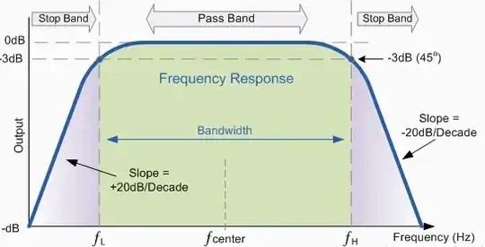
F(low) is determined by the level changing circuit described first and F(high) is determined by the 1kohm and 10nF after the first circuit: -
Andy aka
- 434,556
- 28
- 351
- 777