12

I've asked a couple of questions relating to this project the past couple of days, but I cant seem to put it all together.

I hooked up an electret mic into an opamp and gave output to my arduino microcontroller. The ADC on the microcontroller converts a range of 0 to 5 vV to a 10-bit number (0 to 1023).

I tried 3 different amp chips:

  • LM386 - I got feedback this chip was no good for this purpose, since its not opamp, and it didn't work correctly as expected.
  • LM358 - works
  • UA741 - works, amplifies more than LM358

I followed this schematic exactly (except for I messed around with resistor values to get good gain): I used 50k ohm for R5 and 10 ohm for R2. enter image description here

The problem is that the output from the latter two chips is not "clean". The analogRead() on the Arduino is always reading a non-zero value even when I make no noise in the mic. The reading reacts properly when I make noise, but the "zero" value is non-zero. Sometimes the "zero" value even flickers throwing off the reading all the time. Hopefully that made sense.

Can you help me sort this out?

Just as unimportant, extra information: I'm trying to make something like this, eventually.

Shubham
  • 6,054
  • 12
  • 41
  • 55
  • You are certain you have C2 in place? What is the silent DC voltage after C2? – Majenko Jul 09 '11 at 23:51
  • Yes I have C2 in place. It's about 2 volts. I dont know if this makes any sense: could it be that there is some current trapped(?) in the loop between pin 2 and 6, the output and inverting input? – Shubham Jul 10 '11 at 00:55
  • How about the silent DC voltage after C2 with it disconnected from the Arduino input pin? – Majenko Jul 10 '11 at 08:48
  • The presence of C2 means that the output of the preamp will be swinging around 0V - not 2.5V which it is operating at internally. – Majenko Jul 10 '11 at 08:49
  • One other thing - you may want to slip a little shottky diode in between the pre-amp C2 and the Arduino input - throw away those negative voltages that you really don't care about. One more thing I did was to add another capacitor between the analog input and ground to smooth the signal out a bit. Makes the VU meter a little less flickery. – Majenko Jul 10 '11 at 08:53
  • Oh, and when dealing with the input value, take the square root of it - it represents more what you're hearing (logarithmic) rather than what is being sampled (linear). Rather than doing heavy calculations I just used a little lookup table, – Majenko Jul 10 '11 at 08:54
  • @Majenko you aren't going to get negative voltages; that op-amp is run off a unipolar supply. – akohlsmith Oct 05 '12 at 15:37
  • Just a note about schematic drawn on first picture. You are used 27k resistors to make offset of 1/2 VDC and then put C3 on output. This is good for microphone preamplifier, but it's not good for connecting to ADC becouse you need offset you created. So if anybody tries to connect this circuit to ADC remove C3 if you wish to zero fluctuate ~512 or your zero will be fluctuating around GND. –  Oct 04 '12 at 10:06

3 Answers3

17

Get rid of the output capacitor. That circuit was probably meant to produce a signal around zero, so the capacitor is there to block the 1/2 Vdd offset. However, the microcontroller wants to see the signal centered around 1/2 Vdd, so just get rid of the capacitor.

Microcphones do need a lot of gain. Electrets can be sensitive, but you still might need a voltage gain of 1000. The gain in your circuit is the ratio of R5 to R2, but this only works within limits of what the opamp can do.

The values you mentioned above would give you a gain of 5000. That's a lot more than you should try to get from a single opamp stage. Not only will the offset voltage be multiplied by this gain, but the opamp won't be able to provide that over the full frequency range. At 1 MHz gain-bandwidth, you'll only get that gain somewhat below 200 Hz. Even a 1 mV input offset becomes 5 V after amplification by 5000.

R2 is also the impedance seen by the microphone after the input capacitor. You need this to be somewhat larger than the impedance of the microphone with its pullup and the input capacitor at the lowest frequency of interest. 10 Ω is way too small for that. 10 kΩ would be a better value.

Try two stages with a gain of 30 or so for starters and see where that gets you. That's a gain it can handle over reasonable frequencies with enough headroom left for the feedback to work. You also need to capacitively couple the two stages so that the input offset voltage does not accumulate thru all the stages.

Edit: Added circuit

I didn't have time to draw a circuit last night when I wrote the reply above. Here is a circuit that should do it:

This has a voltage gain of roughly 1000, which should be sufficient for a reasonable electret microphone. I may be a little too much, but its easy to add some attenuation.

The topology is rather different from your circuit. The most important single thing to note is that it doesn't try to produce the whole gain in one stage. Each stage has a gain of about 31. That leaves plenty of gain headroom at the maximum audio frequency of 20 kHz for the feedback, so the gain will be nicely predictable and flat accross the audio frequency range since the MCP6022 has a typical gain-bandwidth product of 10 MHz. The limiting factor will most likely be the microphone.

Unlike what I said before, the two stages do not need to be capacitively coupled to prevent the offset voltage accumulating along with the gain. That is because in this circuit, each stage has only a DC gain of 1, so the final offset is only twice the opamp offset. These opamps have only 500 µV offset, so the final offset is only 1 mV due to the opamps. There will be more due to the mismatch of R3 and R4. In any case, the output DC will be plenty close enough to 1/2 the supply to not eat into the A/D range in a meaningful way.

The DC gain of 1 per stage is achieved by capacitively coupling the feedback divider path to ground. The capacitor blocks DC, so each stage is just a unity follower for DC. The full AC gain is realized as the capacitor (C3 in the first stage) impedance gets small compared to the lower divider resistor (R7 in the first stage). This starts to happen at about 16 Hz. One drawback to this approach is that the time constant to settle is C3 times R7+R5, not just R7. This circuit will take a couple of seconds or so to stabalize after being turned on.

Olin Lathrop
  • 310,974
  • 36
  • 428
  • 915
  • When I take out the cap from the output, the arduino sees an input of about 3 volts. I'm sorry, but can you explain what you mean by offset voltage? To get a gain of 1000, with R2 being 10k Ohm, I need 10M ohm for R5? Are you sure about this? The gain is the ratio between R5 and R2 right? – Shubham Jul 10 '11 at 01:02
  • @Shubham: Your circuit is tries to multiply the opamp's offset voltage by 5000, so it's no surprise the output is pegged to one rail. No opamp is perfect. The input offset voltage is the voltage between the two inputs when the output is mid range. In theory the two inputs would be equal then. The input offset voltage spec tells you how far off it is from this ideal. – Olin Lathrop Jul 10 '11 at 13:53
  • @Shubham: You would need 10 MOhm for the feedback resistor if you tried to have one stage produce all the gain. As I said, that's a bad idea. – Olin Lathrop Jul 10 '11 at 13:54
  • Thanks for all the help, learning a lot here. So having two stages of 30 gain each gives me a total gain of 900, right? I will try this using an LM358 (thats what I have lying around), and report back – Shubham Jul 10 '11 at 18:45
  • Finally it worked! Thank You for giving me that schematic! But I'm only getting an ADC range of about 200. The silent ADC value will be a little above the midpoint (512), but not matter how much noise I make in the mic, the ADC value will not go more than 200 above the silent value. It is probably my setup of caps and resistors that is limiting this. – Shubham Jul 12 '11 at 02:37
  • So I have 2 questions: I didn't use the exact values you have in your schematic, but I tried to get as close as I could. Can I increase or decrease a cap or resistor to increase the ADC range? Also, will the ADC ALWAYS get an input that is higher than the middle point (512)? – Shubham Jul 12 '11 at 02:39
  • Also I am curious: What does C5 acutally do? Sorry, I love asking questions, hope you don't mind me spamming you..haha. – Shubham Jul 12 '11 at 02:41
  • C5 is a decoupling capacitor. It's bypassing the Vcc and Vee inputs of the op amp. – ajs410 Jul 12 '11 at 05:35
  • @Shubham: It sounds like you need more gain. 1000 is usually enough for a electret, but maybe yours needs more. Or, maybe the substituted part values aren't giving your circuit the intended gain. Show the schematic *as you built it* so we can comment. 512 should be the quiet level. The reading should go both above and below that when the mic picks up sound. Ajs410 is correct, C5 is a decoupling cap. Don't try to play games and leave it off just because you don't understand what it does. – Olin Lathrop Jul 12 '11 at 12:47
  • @Olin Here is an exact schematic of what I did: [link](http://lh5.googleusercontent.com/-7B0VY5l528Y/Thx-rhRKJQI/AAAAAAAAANQ/igeopOOkq5w/VU_Meter.png) Oh ok, yea I left the decoupling capacitor there. BTW, what schematic software do you use? I used TinyCad, but I like your schematic – Shubham Jul 12 '11 at 17:06
  • @Shubham: You changed a bunch of values around, so there will be issues. You are now asking for a gain of 101 from the first stage. I don't think that's a good idea, but I haven't looked up your opamp. This will also cause the circuit over 3 times longer to settle from power on. The second stage is set for a gain of 11, but the low frequency rolloff is now much higher since you changed the impedances. – Olin Lathrop Jul 12 '11 at 17:50
  • @Olin: Yea I tried my best to match your values, but I have a box of assorted parts in which I couldn't find exactly what I needed. Does that mean I'm amplifying by 101x11 = 1111? Why is it 101 and 11, and not 100 and 10? – Shubham Jul 12 '11 at 18:22
  • @Shubham: Yes, and the gain is (R1 + R2) / R2 = R1/R2 + 1, not just R1/R2. Think about the circuit, understand how it works, and this will make sense. – Olin Lathrop Jul 12 '11 at 19:53
5

As you say, the digital value will be from 0 to 1023. The middle of this range is not 0, it is 512 (which corresponds to a voltage of around 2.5). For silence, you should see something around the middle of the range like this. Doesn't have to be 512 exactly, but it should be close. This is called "DC offset". The signal is shifted upward and centered around 2.5 V.

If you're measuring 2 V and seeing ADC values around 400, then it's basically working fine.

The sound waves go from negative to positive pressure. If the center point were 0, and the signal could only be measured between 0 and 1023, then negative pressure values (-1023) would be cut off.

Also, it will always fluctuate a little due to the noise floor of the ADC. (And there will always be some audio noise in the room no matter how quiet you are.)

endolith
  • 28,494
  • 23
  • 117
  • 181
  • Ohhh that explains "DC offset" I kept seeing in other answers. Is there a way to remove the DC offset but putting a cap somewhere? – Shubham Jul 10 '11 at 05:52
  • @Shubham: You *WANT* a DC offset. The ADC process won't work without one. The cap C2 is what ensures that you have one. In this case there's probably not much difference, though, because the output of U1 is already offset. Can you measure the DC value on each side of C2? – endolith Jul 11 '11 at 14:32
  • @Shubham: If you mean that you want your digital measurements centered around 0 instead of 512, you can simply subtract the offset in your software, or better, implement a digital high-pass filter in software. – endolith Jul 11 '11 at 14:34
3

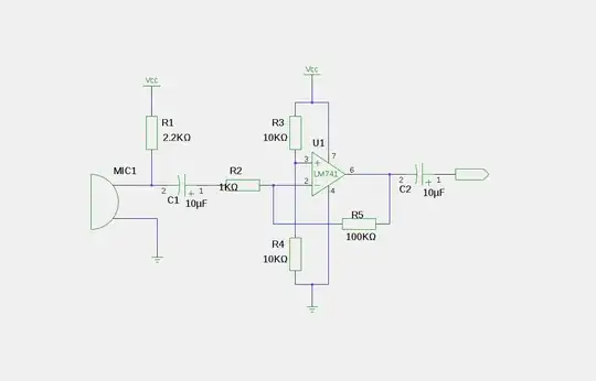
Can you post the spec sheet on that microphone? There is no reason you should need a gain of 5000 with a electret mic unless you have a bare unit with no internal FET. If that is the case the preamp needs to look much differently.

Additionally the circuit you used isn't terribly conducive to being used as a pre-amp for an electret mic.
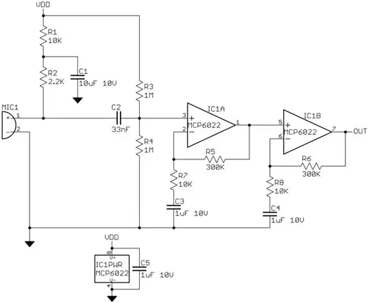
I'd recommend:

enter image description here

R5/R4 sets the gain and can be adjusted without screwing with the input impedance of the circuit. R3 can be from 2k -> 10k ish. 10k will tend to improve distortion performance, if you adjust this too low you should rethink the values for R1 and R2 to fix the input impedance.

Its also very important that the power supply is adequately decoupled as any noise will feed into the microphone.

As the other answers mentioned your "zero" point will be ~512 when you read the ADC and will fluctuate a bit no matter what you do.

If your goal is blinking lights in response to level you shouldn't be taking instantaneous readings with an arduino anyway since i doubt your going to be able to sample fast enough to make it respond well. Instead do peak or average level detection in the analog domain and set the averaging period proportionally to whatever your sampling rate will be.

EDIT: More on doing this with a peak detector

The issue you will have here is that the arduino has a relatively limited sampling rate, I think your maximum is going to be about 10khz which means you can only resolve a 5khz audio signal max. That is with the arduino doing very little except running the ADC, if you need to do any real work (and you do some to get level) the sampling rate will be lower.

Remember your taking discrete samples of the raw signal, just because you have a full range sine wave feeding into the ADC doesn't mean you won't get readings of 0 from the ADC, you'll get samples at various points of the wave. With real music the resulting signal will be quite complex and you'll have samples all over the place.

Now, if all you are trying to measure is the level of the input signal, and don't care about actually getting a digital representation of the signal, then you can use a simple peak detector after this pre-amp to do so.

What this does it turn your audio signal into a voltage that represents its peak level. When you measure this voltage with the ADC you'll have an immediate value representing the level of the signal at the time the reading was taken. You'll still have a bit of wobbling as sound is a complex, always varying waveform, but this should be easy to deal with in software.

A peak detector without hold is really just a rectifier with a filter on the output. In this case we need to deal with low level signals and maintain accuracy so we need to do a little bit more than what would be done for your average rectifier circuit. This family of circuits is called "precision rectifiers".

enter image description here

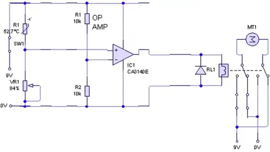
There are about a billion different ways to do this but I'd go with this circuit, it seems to work best when using a single supply. This would go after the pre-amp circuit already discussed and the input could be AC coupled or not, despite it running from a single supply it will actually work just fine with negative input voltages as long as you don't exceed the available peak-to-peak voltage from the op amps.

OP1 acts as a (nearly) ideal diode which gets around the usual issue of voltage drop across the diode when rectifying. Almost any small signal diode will work for D1, something with a lower forward voltage drop would increase accuracy but I doubt it will matter for your use.

C1 and R4 act as a low pass filter to smooth the output, you can play with their values to match up the performance to what your trying to do (and your sampling rate).

You can probably use the same op amp model your using in the pre-amp but Rail-to-Rail and high slew rate are ideal for this circuit. If you have a stability issue increase R1,R2 and R3 to 100k ohm.

Mark
  • 11,627
  • 1
  • 31
  • 38
  • The mic is a standard electret condenser mic. I will make R3 10K, my Vcc is 5.9V so will it be ok if R1 and R2 are 10K too? What opamp would you recommend: LM358 or 741? Is there a way I can bring the "zero" point down to 0 or near 0? "Instead do peak or average level detection in the analog domain and set the averaging period proportionally to whatever your sampling rate will be." - Can you give me a little more detail on this? it sounds interesting and I really want to look into it. Sorry I have to many questions...I'm a EE student in college still learning. – Shubham Jul 10 '11 at 06:02
  • I tried your recommended circuit (it's much cleaner than what I was using, less randomness in output). I used 1M Ohm for R5 and 1k Ohm for R4, giving an amplification of 1000. When I did some measurements with a DMM, the opamp is giving a silent output of about 3 volts, and C3 reduces it down to about 1.5 volts. Also when I remove R5, it doesn't make any difference to the output...are you sure the gain is R4/R5? – Shubham Jul 10 '11 at 06:44
  • 1
    R3 sets the bias point of the FET inside the microphone, (R1 || R2) || R3 sets the AC input impedance seen by the microphone. Setting the "zero" point to 0 can't be solved by anything in the analog domain, that's a function of the ADC in the arduino having a single power supply. All you have to do is subtract ~512 from each sample if you want no sound to be zero (make sure you use a signed data type as this means negative values are possible) – Mark Jul 10 '11 at 08:02
  • R4/R5 is the gain, however a gain of 1000 may be past the limits of the opamp at the frequency you tested. C2 in the circuit is just there to help mitigate any DC offset in the output from feeding back and doesn't impact gain. – Mark Jul 10 '11 at 08:04
  • Mark, C1 against R1//R2 has a 1.3 kHz high pass filter rolloff frequency. That's well above a good fraction of voice frequencies and 6 octaves above the "HiFi" lower limit. This may be fine if he just wants to make a sound activated trigger, but not good if he wants normal digitized sound. – Olin Lathrop Jul 10 '11 at 14:13
  • @Olin you may want to check your math on that, 1/(2*pi*13,500*2.2e-6) = 5.35 Hz. – Mark Jul 10 '11 at 17:03
  • @Mark: I have no idea now how I got that 1.3 kHz value. I get 5.4 Hz now too. I must have punched the wrong key somewhere. Sorry for the confusion. – Olin Lathrop Jul 10 '11 at 17:27
  • @Shubham I added more on using a peak detection circuit for what your trying to do. – Mark Jul 10 '11 at 22:24