4

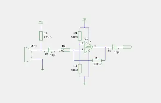
I followed the mic + op-Amp part of this schematic exactly using an Lm386 chip: https://randomskk.net/projects/lightstrip/schematic.pdf

and sent the output from the op-amp into a pin on an Arduino Pro Mini. BUT, when do an analogRead(pin) and print the value in the serial monitor, the value seems to level out to some constant, no matter how much noise I make into the mic!

Can someone tell me what I could be doing wrong?

As extra information: I left out the capacitor on pin 7 of the IC that is shown in the schematic.
And the power supply I'm using is my old phone charger that plugs into the wall and outputs 5.9V DC. I am trying to make this:
http://www.youtube.com/watch?v=Km6ObG_xKm4

Also, how do you tell the anode and cathode on an electret microphone?

Thanks!

Shubham
  • 6,054
  • 12
  • 41
  • 55
  • Where is the feedback round the op-amp? And the input resistor? I'm mightilly confused by that circuit. – Majenko Jul 08 '11 at 15:40
  • Normally there's a little circle around the positive lead on the mic, but this will depend on the manufacturer. If you are not sure, you'll probably have to check the datasheet – Jim Jul 08 '11 at 15:49
  • 1
    @Matt - like Jim said, the LM386 is not an opamp, you don't need the feedback. See [datasheet](http://www.national.com/ds/LM/LM386.pdf) – stevenvh Jul 08 '11 at 15:50
  • @stevenvh Ah yes, of course it isn't - silly me. – Majenko Jul 08 '11 at 15:50
  • Can you please explain the difference between OpAmp and power amp for audio to me? This may be where I'm going wrong. If this is the case, is it possible to do what I'm trying to do using LM386L? – Shubham Jul 08 '11 at 16:01
  • 1
    @Shubham - It's definitely not typical use of the LM386. Normally you would use it to drive a speaker, and as a power amplifier it has limited gain, in your schematic x200, which may be too little to get a decent amplification for the low signal from a microphone. With an opamp you can get much higher amplifications. – stevenvh Jul 08 '11 at 16:46
  • Thanks so much guys, all of your answers and comments explain a lot! I will try this with an actual op-amp IC (LM358) when I get home today! – Shubham Jul 08 '11 at 22:36

4 Answers4

5

Personally I'd have the input more like this:

enter image description here

That will provide 100x amplification. If you want less then increase R2 or decrease R5. If you want more then decrease R2 or increase R5.

It may not be a 100% perfect circuit, but it's one I have used successfully.

Majenko
  • 55,955
  • 9
  • 105
  • 187
  • Thanks Matt I want to try this setup, but I don't have a lm741. Can I still use my LM386L chip with this schematic? I also have an LM358 which IS an operational amplifier (I looked up the data sheet just now), can I use that? – Shubham Jul 08 '11 at 16:21
  • the 385 should be ok, but not the 386L iirc – Majenko Jul 08 '11 at 16:28
  • I found an LM741 in my box of electronic stuff! And it worked like a charm with your schematic But the problem is that when I read the analog input in the arduino, the minimum value is about 600, meaning when there is no sound, its 600. How can I lower this so I get a larger range from quite to loud? – Shubham Jul 09 '11 at 02:55
2

You may want to look at how you have wired pin 7, it's a bypass for the amp, if you have it connected it may be shutting off the LM386 IC.

BTW, the LM386n is not the same as an operational amplifier- it's a power amplifier for audio applications and does not require a split power supply.

Jim
  • 3,325
  • 2
  • 28
  • 39
  • I left pin 7 untouched, its not hooked up to anything. I'm using an LM386L chip. Ohhhhhhh I didn't know op amp and power amp for audio was different. Ok I have another an opAmp chip I will try out with. – Shubham Jul 08 '11 at 15:59
  • I think the circuit suggested by Matt may give you a better result, there's no reason this particular chip wont be apropriate, you probably just need to crank the gain. Maybe you could try with a multimeter to see if shouting at it is getting the desired output strength. – Jim Jul 08 '11 at 16:08
2

What value are you getting on your serial port?

There's a couple things I noticed with this circuit:

  1. No coupling capacitor on the output of the amplifier - there should be one here to block any potential DC offset and it's good practice to have one in between stages.

  2. You mentioned that you didn't use the bypass capacitor on pin 7, and as others have mentioned, I would think it's a good idea to have one here.

If your ADC value is hitting its ceiling (which is 1023 on a 10-bit ADC), I would guess the problem may be with DC offset.


EDIT: In response to comment below, even though I don't think DC offset is the issue here given differing values on the ADC each time.

DC offset is when an AC signal has a DC component to it, which is essentially a summing effect. The best way to visualize DC offset is if a wave (your signal) were shifted upwards or downwards but the peak-to-peak amplitude of the wave is unchanged. Take a look at this image:

enter image description here

Adding a capacitor in series will eliminate this offset because the impedance or "resistance" of a capacitor is very high at DC frequency (which is 0 Hz). There is a coupling capacitor after the microphone in that schematic for this exact reason, and after a gain stage, it is a good idea to have one as well. If your ADC is settling to some random value less than 1023 every time, then I'm guessing the issue is else where, but this is good practice when connecting various stages.

Jon L
  • 4,258
  • 1
  • 22
  • 33
  • The value is different every time, but it levels out to a constant when I power the circuit. Sorry, I'm still a total noob at all this. Still learning about what coupling is, pass filters, etc... What do you mean by DC Offset? (What is it?) – Shubham Jul 08 '11 at 17:13
  • @Shubham, hey no worries, we all have to start somewhere. DC offset is when an AC signal has a DC component to it, which is essentially a summing effect. I'll edit the answer to provide a better explanation... but I'm sure you can get a quality answer to that particular question by making it a stand-alone question as well. – Jon L Jul 08 '11 at 18:19
1

You pin 5 of amplifier output is DC coupled to some CMOS or ADC I assume chip. Not good. The load should have resistive impedance and AC coupled. Add capacitor in series to to output and 2 equal resitors 200-2000 ohm each. One to ground and one to power.

  • Yes the amp output is going into an arduino. Can you please be more specific and explain why its bad and why I should add a cap and 2 resistors? I'm new, this is only my second arduino project. – Shubham Jul 08 '11 at 17:50