I am currently working on an embedded audio processor project based on the stm32f4discovery board and the wm8731 codec from cirrus/wolfson.
I was wondering if anyone here is familiar with the codec in question. Through my own research, I've come to find the codec is renowned for having documentation that is difficult to understand.
My issue is specifically with the VMID pin. The recommended external connections on the datasheet found here http://www.cirrus.com/en/pubs/proDatasheet/WM8731_v4.9.pdf (pg 60) show two parallel capacitors to ground. However, the datasheet (pg 22) mentions that VMID is responsible for internally biasing incoming signals.
When searching online I came across a similar project by Eric Brombaugh at http://ebrombaugh.studionebula.com/synth/stm32f4_codec_v2/stm32f4_codec_v2_schematic.pdf where VMID was wired as in the datasheet. I don't understand why this is because there is no added DC offset on the two LINEIN inputs.
Am I missing something here? Do I need to supply a voltage to VMID to bias my inputs? Or is it done regardless? Also, is it possible to just add the offset to the inputs myself prior to the codec ADC's?
Edit/update From the replies below it is now clear that a DC offset on analog inputs is not necessary, but this gave rise to another query. Initially, because of previous experience with other ADC's, I approached the input design under the notion that it was.
The inputs were to take a signal from an electric guitar, amplify it and then add an offset (redundant now). This is shown in the schematic below.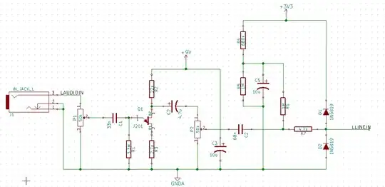
The preamp is of the common source self biased topology based on the j201 JFET. The potentiometer P2's purpose is to attenuate some of the gain so that the AC swing could be limited between -1.65v and +1.65v. The next stage is a voltage divider that adds dc offset to bring AC swing to 0 - 3.3v This was one of the methods mentioned in another question shown on the page DC biasing audio signal
Before this revision, R4, R5 and R6 were all 100k values, which in theory is perfectly fine. What I found was that when I connected R6 to just after C2, to add the bias, most of the gain from the preamp stage was attenuated. This was because adding the DC offset stage loaded down the lower half of the voltage divider created by P2. The solution was to change the values of the resistors so that they would be much larger than the potentiometer. This fixed the gain issue, but I then found the dc offset was slightly off. I then had to decrease R4 to get the clean 1.65v I needed.
The reason I explain all of this is because I now wonder if removing my dc offset stage and connecting it to the codec LINEIN will have a similar effect. If so, I wouldn't be able to adjust the internal resistor values of the codec to compensate.
Please let me know of any misconceptions you think I may have.