I am trying to combine logic gates (using ICs instead of trying to piece them together using transistors or MOSFETs). Below is the simplest example of what I am trying to accomplish, though ultimately I would like to be able to combine 10 or more logic gates together in series. In short, the problem I have is anytime I have an output from one of my gates it shows the appropriate voltage, but immediately when I connect that output to an input of another successive gate the voltage on that gate is almost cut in half resulting in the input being somewhere between high and low. I looked at this post and read it over a few times, but am not able to apply the answer to my problem especially if I want to create a network of logic gates rather than just combining a NOR and NOT to get an OR. I also don't have a firm understanding of TTL, which is why I am using IC packages.
simulate this circuit – Schematic created using CircuitLab
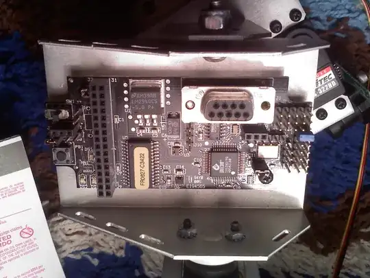
When I breadboard this out using +5V as high, I get something like this:
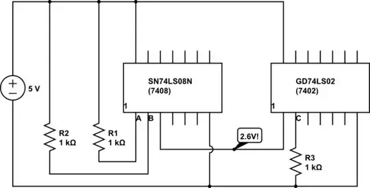
Again, when I leave the output of the 7408 open and look at the voltage it is 5V, but immediately when i connect that output to the input of the 7402, the voltage drops to 2.6V.
I have a feeling that I am missing something pretty basic here but have rebuilt circuits like this several different times with different gate combinations and see the same thing occur when I try to take a logic 1 output from one gate and feed it as a logic 1 to the input of another.
Am I using the ICs properly? Can anyone tell me why the voltage is dropping between the gates?
Thanks for taking the time to read this.