1

If I have two devices that some distance apart on a fairly large PCB (could be 1 in, or it could be 20 in). If I arbitrary select a value for R1, lets say 33 ohms in this example and if my digital signal is distorted due to reflection, how can I determine if I should increase or decrease my resistance to get my digital signal correct ? What indicators when I look on a scope, should be key characteristics that my voltage divider ratio is too high or too low (referring to source impedance + R1 and Zo)

Assume that the characteristic impedance (ADD: of the trace) is (ADD: constant but) not controlled (ADD: / known).

schematic

simulate this circuit – Schematic created using CircuitLab

Rolf Ostergaard
  • 4,448
  • 18
  • 24
efox29
  • 11,827
  • 9
  • 56
  • 102

3 Answers3

2

Measured at the receiver end:

  • Undershoot means your series termination resistor value is too big
  • Overshoot means your series termination resistor value is too small

For low-to-high edges there is only one definition of overshoot and undershoot, so that's the one used here. I like to use a similar definition for high-to-low edges, but not all agree so be careful.

Rolf Ostergaard
  • 4,448
  • 18
  • 24
1

The purpose of the source terminator is to damp the initial reflection from the end of the line when it returns to the source. The easiest way to pick The right one is to find the output impedance of your driver and then use the resistor to match that to the line impedance.

Here's another question that addresses this.

I think if you terminate too low your reflection coefficient is negative so the reflection will come out inverted. That older question seems to agree.

Occasionally you will also see people use high value series terminators to try and slow down an edge for emi. Not the best for ringing of course.

Some Hardware Guy
  • 15,815
  • 1
  • 31
  • 44
0

Any reflections that might distort your originating signal depend on the terminating impedance of the cable and not on a resistor placed in series with one of the cable wires. Also, if your originating signal is a true voltage source, the effect of reflections, at that voltage source will be zero.

I'll also add that if the originating source is not a perfect voltage source i.e. it has a finite impedance, you'll only see distortion if the originating signal is NOT a sinewave. In the case of a sinewave you might see modifications to its amplitude but no distortion.


EDIT - this demo is for Nick so he can understand what I'm saying: -

enter image description here

Animated picture taken from here

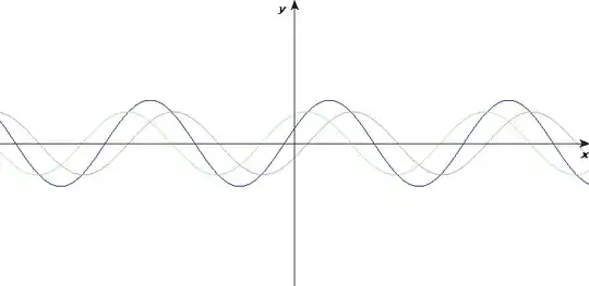
Red is the forward sine wave travelling down a cable from left to right. Green is the reflected sine wave travelling back up the cable to the originating source. Blue is the standing wave - the standing wave (at any fixed point on the cable) is actually a constant amplitude sine wave of the same frequency as the originating wave but at points along the cable it will have zero amplitude and at other points it will have maximum amplitude.

The blue trace looks like a modulated sine wave BUT IT ISN'T. It's a standing wave and predicts what the RMS amplitude of the combined forward and relected signals are at various points along the cable.

As for the rest of this question, without understanding the end-termination impedances of the cable, any amount of series resistance is just speculation and I'm surprised other answers haven't addressed this because it is of fundamental importance to the question.

Andy aka
  • 434,556
  • 28
  • 351
  • 777
  • It's not a cable. It's a trace on a really big board. What is a "true voltage source" ? – efox29 Apr 05 '15 at 23:32
  • Hm, then why do people add series termination of 33 ohm (if source impedance is 7-8 ohm) on a controlled 50 ohm trace for a high speed digital line ? Perhaps my question didn't imply digital signal (I'll edit). – efox29 Apr 05 '15 at 23:37
  • Cable or traces on PCB make no difference because they act identically. A true voltage source produces a signal that cannot be distorted or reduced in amplitude. A non true voltage source is a true voltage source in series with an impedance. – Andy aka Apr 05 '15 at 23:38
  • Well this would be a non true source, because these are coming from ICs (microcontroller to some logic device). – efox29 Apr 05 '15 at 23:40
  • Then you need to specify exactly what your situation is in your question. – Andy aka Apr 05 '15 at 23:42
  • Ampltitude modulation of a sine wave _is_ distortion, in the frequency domain. – Nick Johnson Apr 06 '15 at 09:27
  • @nick who mentioned modulation? – Andy aka Apr 06 '15 at 10:02
  • @Andyaka You said "you may see modifications to its amplitude" - which is AM. You can't 'modify' a signal's amplitude without adding additional frequency components (Eg, distortion). – Nick Johnson Apr 06 '15 at 10:04
  • @nick I'm not talking about repetitive modulation. I'm talking about a fixed in time increase or decrease in amplitude. – Andy aka Apr 06 '15 at 10:08
  • @Andyaka It doesn't matter - that's still distortion. In fact, the shorter the period of the 'increase of amplitude' is, the higher the frequency of the distortion. – Nick Johnson Apr 06 '15 at 10:14
  • @nick I don't think you are following what I'm saying - for a continuous sinewave applied from a voltage source with output impedance to a transmission line, the voltage seen after the impedance will be a sinewave that has a bigger or smaller amplitude and, this is due to the reflection adding or subtracting. There will be no duration (longer or shorter) - it will be a continuous (but fixed-in-time) modification of the amplitude and not something that would cause the sinewave to become modulated on some cyclic basis. – Andy aka Apr 06 '15 at 10:22
  • @nick - I've modified my answer to hopefully explain my point. – Andy aka Apr 06 '15 at 10:55
  • Yes, fair enough. I thought you were talking about a transient condition; if all you send is a sine wave, then of course it won't be distorted. – Nick Johnson Apr 06 '15 at 10:57