1

I'm trying to amplify an AC wave (from an audio input) with a maximum amplitude of about 1.8v to a DC oscillation between 0V and 5V with the centre (what would be the zero-crossing on the input) at the midpoint of 2.5V.

I've attempted to use a differential amplifier design to achieve this but my output is inverted from the input.

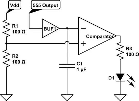
Here's my current schematic from CircuitLab: Schematic

And the simulation output: Simulation

I'd really like it if I could produce a non-inverted output without any additional active components, how could this be done?

Thanks in advance!

CallumA
  • 13
  • 1
  • 1
  • 3
  • So you want the DC output voltage (i.e. with no AC input) equal to 2.5V? And gain of +2.5/1.8 = +1.38 instead of -1.38 as you have? – Null Apr 02 '15 at 19:26
  • @Null Yeah, that's it – CallumA Apr 02 '15 at 23:42
  • possible duplicate of [Level shifting a +/- 2.5V signal to 0 - 5V](http://electronics.stackexchange.com/questions/37095/level-shifting-a-2-5v-signal-to-0-5v) – Greg d'Eon Apr 03 '15 at 02:32

1 Answers1

4

Easiest method:

schematic

simulate this circuit – Schematic created using CircuitLab

Component values are left for you to calculate.

Note that the TL081 is NOT an appropriate op-amp, given your desire for a rail-to-rail output swing.

R1 & R2 set the op-amp bias point.

R1, R2, C2 forms a low-pass filter that reduces noise from the power supply

R5 sets the input impedance

R5 & C3 set the input hi=pass filter time constant

R3 & R4 set the gain.

R3 & C1 set the gain-set section hi-pass filter time constant.

Note that if you are not concerned about noise from the power supply line getting into your amplified signal, you can eliminate C2 & R5. In that case, R1 & R2 set the input impedance and R1, R2, C3 set the input hi-pass filter time constant.

Dwayne Reid
  • 23,390
  • 2
  • 35
  • 67