3

I need an AC to DC converter circuit where it is safe to connect common to ground.

My situation: I have a remote 120v->24v transformer. The 24v neutral is grounded. The DC circuitry is the only load on the transformer. The common node must be grounded for a communications bus.

What AC to DC converting circuits will allow you to connect common to ground?

stevenvh
  • 145,145
  • 21
  • 455
  • 667
Chris S
  • 133
  • 1
  • 6
  • Whoops! There *was* a question in my first edit, but it was hard to spot. Fixed it to be more explicit - Sorry for the confusion! If you're confused by my first edit, there's no need to apologize for a question, point out your skill level, or request anything less than a full answer. – Kevin Vermeer Jul 01 '11 at 19:56
  • Also, no need to try to hide your concern about my edit. I try to help, but I'm still human: Constructive criticism is welcome! – Kevin Vermeer Jul 01 '11 at 20:00
  • what sort of DC voltage are you aiming for? – JustJeff Jul 02 '11 at 01:33
  • @JustJeff, anything between 5 and 48 VDC. I've got a dual linear reg that operates up to 48v cutting the voltage down to 3.3v and 5v for the ICs. – Chris S Jul 02 '11 at 03:16
  • @Steven, my apologies for not being specific enough before, the regulator needs 5.7 to 42.0 VDC; it's the [Infineon TLE4476](http://goo.gl/s90WY). Kevin cut out the mention that I'm a hobbyist, and usually use much simpler power supplies (like a store bought brick). The circuit it's driving will take a max/typ of 300/200mA 3.3v and 350/30mA 5.5v. There will eventually be quite a few of these loads on the transformer/power supply circuitry. – Chris S Jul 02 '11 at 23:33
  • @Chris - with the current transformer and the voltages/currents you mention the TLE4476 would have to cope with more than 18W, what it never will be able to. I updated my answer with a suggestion for an SMPS. – stevenvh Jul 03 '11 at 09:12

1 Answers1

5

You talk about a "24V neutral", does that mean the center tap, like in JustJeff's interpretation (JustJeff deleted his answer)?

If you do have the center tap this rectifier is the solution, like JustJeff also suggested:

enter image description here

You get a full-wave rectifier (less ripple) and the rectified voltage won't be extremely high: \$V_{OUT} = \frac{24V}{2} \times \sqrt{2} - 1V = 16V\$. (That's still high enough!)
note: center tapped rectifiers don't make efficient use of the transformer, because only half of the transformer is used at any time. A half-wave rectifier has a similar problem: it uses the whole transformer, but only half of the time.

If you don't have the center tap there's a bridge rectifier of a half-wave rectifier. The bridge won't work: there's no point on your transformer which you can connect to the DC's ground without shorting a diode. So you go for the half-wave:

enter image description here

The output peak voltage will be \$V_{OUT} = 24V \times \sqrt{2} - 1V = 33V\$ (that's high!), and it will have some ripple on it. How much depends on the capacitor value and your load. If that's limited to, say, 50mA, a 1000\$\mu\$F cap should take care of that. If your load current is much higher, you not only will have a much larger ripple and need a much larger capacitor (which won't be happy with this ripple), but if you use a linear regulator you'll also lose a lot of power in that. Even at 50mA it will consume 1.4W. A switching regulator is the solution if you want to stick to your current transformer.

If you can switch to another transformer I would pick a 2x8V dingus and use the center tap solution. (Even 2x7V will do, but may be more difficult to find.)


edit
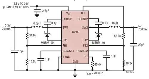
From your comments I understand that you want to limit the current (maybe to limit cable losses?), and therefore rather would use a higher transformer secondary voltage. That's OK, but in that case you definitely need a switching regulator; a linear will cause too much loss. This one may be a possibility:

enter image description here

Other options are two separate switchers, or a switcher for the 5V, followed by an LDO for the 3.3V. All depends on the currents you need at those voltages.
The higher input voltage may also mean that your circuit/network is no longer SELV, if that's important. (I don't quite remember what the maximum DC voltage is for SELV.)

stevenvh
  • 145,145
  • 21
  • 455
  • 667
  • I interpreted OP's use of 'neutral' the same as for a pole transformer, i.e., the center tap. Though I deleted my answer, I'd still endorse this topology as a means to get full-wave rectification under the requirement (for whatever reason) of a grounded center tap. That said, I concur that if OP wants to drive a 3.3V or even a 5V regulator, with any appreciable current, 17V is, well, too much. This is simply the wrong transformer for the job. – JustJeff Jul 02 '11 at 15:27
  • @JustJeff - I had to look up "pole transformer", we don't have these things in Belgium, just 230V (star) and 400V (delta). No [poles](http://bloximages.chicago2.vip.townnews.com/wcfcourier.com/content/tncms/assets/editorial/6/be/f56/6bef56fc-69e8-11df-a12e-001cc4c002e0.image.jpg) either: except for a single remote farm we don't have overhead power lines after the last transformation station; everything goes underground. – stevenvh Jul 02 '11 at 15:48
  • @JustJeff - aesthetically pleasing? Well, we have problems of our own. Many people find Belgium urbanistically fugly, and I kind of agree. But we see the US power infrastructure as --pardon me saying-- rather medieval. :-) – stevenvh Jul 02 '11 at 17:01
  • My apologies again for the horrible terminology. I meant "half-wave" when I said "half-bridge", I was told be someone else that using these exclusively on a transformer will "saturate" it and it will stop working. I have almost no experience in messing with transformers (the initial design was based on a circuit I found on the net using a bridge rectifier, but I realized that wouldn't work with the grounding & wiring requirements. I don't have a transformer yet, still designing this system before buying too many of the parts. – Chris S Jul 02 '11 at 23:41
  • I would consider other transformers and power supply circuity solutions. However there has to be a single point of power entry to the system (a bus with multiple devices on it). I picked 24vac (up to ~36VDC) on the premise that the wiring has to stay under ~0.6A total (slightly flexible), even with a dozen of the above devices (2w/device nominal). More complicated devices are likely to be developed as well, which may have higher power requirements themselves. If this isn't feasible I might have to rethink the wiring requirements. – Chris S Jul 03 '11 at 03:22
  • @stevenvh, wow, I wish I could give more rep for that answer. I think I'm understanding this much better now; and have plenty of reading to do yet. Thank you very much! – Chris S Jul 03 '11 at 13:25