I have designed a Costas Loop for carrier synchronization in MATLAB, here is my code:
% Siraj Muhammad
% 25/3/2015
% BPSK Demodulator
%%%%%%%%%%%%%%%%%%%%%%%%%%%%%%%

load RRC.mat

fc = 0.0500001;
phase_offset = pi/7;

N = length(rf_signal);
bb = zeros(1, N);
bb_f = zeros(1, N);
I_f = zeros(1, N);
Q_f = zeros(1, N);
I_r = zeros(1, N);
Q_r = zeros(1, N);
error = zeros(1, N);
PhErr = zeros(1, N);
error_integral = zeros(1, N);

% Loop Filter Coefficients
C1 = 2^2;
C2 = 1/2^8;

for i = 2:N
    % Downconverting to Baseband
    bb(i) = rf_signal(i).*exp(j*2*pi*fc*i+j*phase_offset).*exp(-j*PhErr(i-1));

    % Filtering
    bb_f = filter(RRC, bb(1:i));
    I_f = real(bb_f);
    Q_f = imag(bb_f);

    % Slicing
    I_d = sign(I_f(i));
    Q_d = sign(Q_f(i));

    % Error
    error(i) = I_d.*Q_f(i);

    % Loop Filter
    error_integral(i) = error(i).*C1 + error_integral(i-1);
    PhErr(i) = (error(i).*C2 + error_integral(i))/2^5;
end

figure; subplot 321; plot(real(bb)); title('I Channel')
subplot 322; plot(imag(bb)); title('Q Channel')
subplot 323; plot(I_f); title('I Channel Filter')
subplot 324; plot(Q_f); title('Q Channel Filter')
subplot 325; plot(error); title('Phase Error');
subplot 326; plot(PhErr); title('Loop Filter');
rf_signal is generated in another MATLAB script that produces BPSK signal. Simulation in MATLAB shows good results, loop tracks phase and frequency and locks on them.
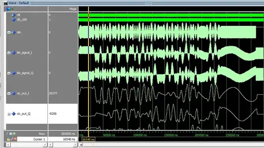
After I verified the design, I implemented it in VHDL using some Altera MegaCores. However, ModelSim simulation doesn't show the expected result. Loop seems to oscillate rather than locking, even though the loop is closed.
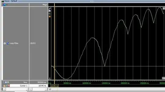
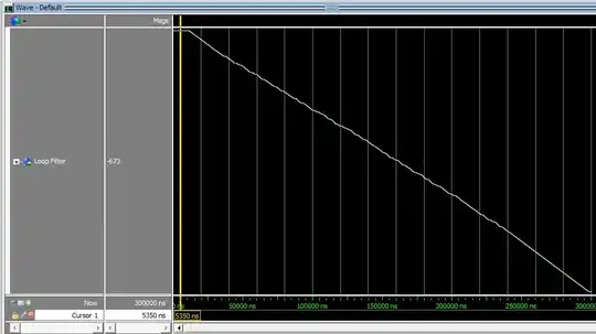
And this is the loop filter's output, you can see how it is oscillating.
I checked all signals widths and made sure that they do not overflow. When I open the loop in MATLAB and ModelSim, I get the same loop filter output.
They are opposite because data is modulated with cosine in MATLAB and sine in ModelSim. Problem is when the loop is closed.
Any advice would be appreciated.