7

Quoting from wikipedia:

"In one simple inverter circuit, DC power is connected to a transformer through the centre tap of the primary winding. A switch is rapidly switched back and forth to allow current to flow back to the DC source following two alternate paths through one end of the primary winding and then the other"

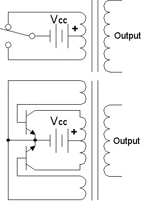
Also given in this article was this example image

Top: Simple inverter circuit shown with an electromechanical switch and automatic equivalent auto-switching device implemented with two transistors and split winding auto-transformer in place of the mechanical switch.

Can anyone explain how the transistor does the switching part needed to produce the AC current? If the 2 transistors alone are only needed to convert DC to AC what's the need of a 555 timer as shown in this circuit at http://www.electronicsforu.com/efylinux/circuit/IC.pdf

Thank you.

zebonaut
  • 18,170
  • 4
  • 60
  • 104

4 Answers4

2

"The upper part of the figure shows a simple inverter configuration in which a bidirectional switch is used to alternate the voltage supply between the two halves of the primary of the transformer. The secondary side of the transformer outputs a voltage square waveform whose amplitude is given by the transformation ratio of the transformer and whose frequency is given by the switching time of the switch.

The lower part of the figure shows an inverter in which the transformer is used also to command the two BJT's. When the upper BJT is in saturation, the transformer primary is subjected to a DC voltage. This voltage is mirrored into the two auxiliary windings which drives the bases of the BJT's. While approaching magnetic saturation, the voltage in these two auxiliary windings falls down and so the upper BJT turns off. Since in the transformer core the H field is not zero, a current must feed the transformer. This causes a rapid voltage inversion across all the transformer windings, which turns on the lower BJT. This cycle repeats indefinitely and causes a square voltage waveform on the secondary output of the transformer." (Source: http://en.wikipedia.org/wiki/File:Inverter_ckt_01cjc.png)

This answers provides some links to relevant literature: What is the use of transformers with 3 pairs of wires?

The power output of a self-oscillating resonant converter like this depends of the saturation characteristics of the ferrite core. Therefore, such circuits are used in special applications like compact fluorescent lamps where precise trimming of the components is worth the effort because every tiny amount of cost counts. If you desire to have a known frequency imposed by an external oscillator, you may want to use something like an external timer IC (555 or the like). Also, resonant converters alone are no controlled devices (except if you like to call the core saturation a means of control). If precise control is required (like in LCD display backlights), the driving current for the resonant converter is often provided by a controlled stage similar to a step-down-converter. This answer provides some literature links on this topic: Electronic Drivers for Fluorescent Lamps: How is the DC-to-AC Conversion done?
Sachin Vasudev
  • 161
  • 1
  • 5
1

The transistors' base voltages come from the extra windings you see in the second picture. I haven't seen that circuit before, but the base-windings are probably wound so that this causes the oscillation. As the current is ramping through one of the two loops the base on the other loop is actuated, and vice versa => oscillation.

With a 555 or similar you have full control over the switching period and waveforms. There are lots of ready-made ICs which drive currents through inductors to induce negative voltage and they are much more flexible than the auto-oscillation in the figure.

Bjorn Wesen
  • 798
  • 1
  • 4
  • 11
1

If the 2 transistors alone are only needed to convert DC to AC...

It's not just the 2 transistors - there are two extra coils in the transformer.

A transformer like this I have never seen. I imagine they are quite rare and expensive. It is much cheaper to use a readily available oscillator such as a 555 timer to do the job.

Plus, it gives you a huge amount more control over how it oscillates - such as the switching frequency.

Majenko
  • 55,955
  • 9
  • 105
  • 187
  • 1
    Actually, the transformers are simple small ring cores with a few windings. They are extremely cheap, much cheaper than a timer IC and the base driving circuitry required to drive the power transistors. A circuit like this is used by the millions in compact fluorescent lamps which are very cost-sensitive because of the huge number that is produced. – zebonaut Jul 09 '11 at 13:01
1

Consider that oscillator is an amplifier with positive feedback.

  • step 1: With one transistor loaded to primary winding, you have AC amplifier
  • step 2: With input coil connected to amplifier you have a feedback
  • step 3: With choosing exactly what polarity of winding is used, you have the feedback being positive
  • step 4: It already works, but you add second shoulder for symmetry
  • step 5: When power is applied circuit does nothing, just amplifies tiny thermal noise
  • step 6: After some take up time, the noise is amplified so well, that it now oscillates with some amplitude close to saturation