6

I'm working with 12V DC systems and high currents (up to ~40A). In order to meet the wattage and price requirements for my design, I'm using two parallel sense resistors. The IC I'm using for sensing is (PN: PAC1710-1-AIA-TR), though this question should be applicable to just about any sensing solution requiring SMD resistors.

I know that when using a SMD resistor for current sensing, this is the ideal layout:

Single resistor

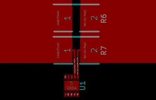
But what about parallel resistors? Which of these two below is ideal, if either? Is there something more I need to consider when applying parallel resistors in this manner?

Take one

Take two

(Also, can anyone provide resources for further reading on this particular topic? I'm usually quite proficient in finding answers to my queries, but I haven't found any useful info on laying out parallel resistors in current sensing applications.)

Jack
  • 61
  • 4

3 Answers3

4

When using parallel resistors (that are adequately matched) I'd consider doing this: -

enter image description here

Andy aka
  • 434,556
  • 28
  • 351
  • 777
1

Sorry for the answer to an old question, but it could use some additions. While Andy is technically correct, it is in fact recommended that current is measured as OP shows in 2nd picture, ie from one sensor, NOT between them.

The reason is twofold:

  1. the current only flows through the resistors, so if you measure between them you do not minimise the conductive path shared between them.
  2. Also, in future if you decide to DNM (do not mount) one resistor, you will have no issue with current flow/heat build up.

More about this can be read in the link HERE

novastorm
  • 111
  • 5
  • Thanks! Can you please elaborate what is meant by "you can connect the sense terminals of multiple resistors together into two common tracks, one for each polarity" in the article you link? – EarthLord Nov 03 '22 at 15:54
  • 1
    It means that you can just connect the sense pins together for each sense resistor and then have one pair of sense tracks to your AFE or current sense amplifier. Here is a bad image I made: https://i.postimg.cc/GtsYB33n/E7994-D45-9-E57-481-E-9048-9-B70-AEFFD2-E2.jpg – novastorm Nov 03 '22 at 19:20
0

The best way is to use a summing amplifier where a connection is made for each parallel resistor. The drawback is that is consumes a bit more space on the PCB.

toolic
  • 5,637
  • 5
  • 20
  • 33