10

I have a 24 VAC Contactor that I want to drive with a microcontroller through a photmos. How do I calculate the proper size resistor and capacitor for a snubber circuit? Here are some of the specifics. Thank you for your help!

Microcontroller - 5V DC 40 mA max on the output pin.

AQV252G Photomos http://www.futureelectronics.com/en/technologies/electromechanical/relays/solid-state-relays/Pages/9530346-AQV252G.aspx?IM=0

Transformer Data - 24 VAC 40 VA Transformer

Contactor Data

Contactor Nominal Coil Voltage 24

Maximum Pickup Volts 18

Drop-Out Volts Range 6 - 15

Nominal Inrush VA @ 60 Hz 20

Nominal Sealed VA @ 60 Hz 5.25

Nominal DC Resistance - Ohms ± 10% 16.5

Superheat
  • 111
  • 1
  • 1
  • 3
  • 1
    http://www.illinoiscapacitor.com/pdf/Papers/arc_suppression.pdf Try this. – user68868 Mar 28 '15 at 16:39
  • 1
    @user68868 if the PDF is displaying correctly on my cell, the logic (if any) behind the equations escapes me. "C=I²/10" how does an amps squared value convert to uF (or F, they don't say which)? How does "R=V/ [10+ (1+ (50/V))]" convert to ohms? These appear to be rules of thumb with units and assumptions omitted and simplifications skipped (R=V/[11+(50/V)]). And why the 50/V term? Above 5V or so it's negligible vs. component tolerances, and I don't think there's a lot of under-1V high current relay switching being done. – Technophile Jul 13 '20 at 01:50

3 Answers3

22

It's actually a bit difficult to calculate the values required for an R-C snubber without knowing something about the amount of energy that needs to be absorbed, which is related to the load current and the load inductance. Often one or both of these values must be guessed, because hard data is not available.

The idea of a snubber is that the capacitor absorbs the inductive energy stored in the load at the moment the switch (photomos) opens, and its value must be large enough so that the voltage across it does not exceed the rating of the switch.

The resistor is there partly for damping and partly to make sure that the capacitor doesn't discharge instantly through the switch the next time it closes. Its resistance value and its power rating must be deduced from the worst-case conditions for both scenarios. The power rating is also related to how frequently the switch is going to be operating.

Note that at the instant the switch opens, the capacitor is discharged and the load current is driven through the resistor, so its value must be low enough so that the IR drop does not exceed the rating of the switch, too.


So, taking what we know about your contactor and your SSR and making a few assumptions along the way, we can come up with some preliminary values.

The steady-state current of your contactor is specified as 5.25 VA, which at 24 V means that the current is

$$\frac{5.25 VA}{24 VAC} = 220 mA (RMS) = 310 mA (peak)$$

Your switch can handle about 60 V. Let's allow a little margin, so we'll design for 50 V. Therefore, if we want to keep the initial voltage across the switch to this level, we need a resistor no larger than:

$$\frac{50 V}{310 mA} = 160 \Omega$$

Let's assume that a medium-sized contactor coil has an inductance of about 1 H. This means that at the peak value of current, it is storing

$$0.5 \cdot 1 H \cdot 310 mA^2 = 48 mJ$$

of energy. Again, we want to limit the voltage across the switch to 50V, so the capacitor must be able to store this energy without exceeding that value:

$$\frac{2 \cdot 48 mJ}{50 V^2} = 40 \mu F$$

Note that this needs to be a nonpolarized capacitor!

Every time the switch cycles, you're dumping 48 mJ of energy into the resistor. If this is happening rarely (e.g., less than once a second), then a 0.5 W resistor will be more than sufficient. However, if it happens a lot more often, a bigger resistor might be called for. For example, 10×/second would represent a power dissipation of 480 mW, which would call for a 1W or larger resistor for robustness.
Dave Tweed
  • 168,369
  • 17
  • 228
  • 393
7

schematic

simulate this circuit – Schematic created using CircuitLab

Excellent answer for design of the R-C snubber. I would like to comment on relatively large capacitor value of 40uF. The reason for this comes from having to limit the voltage to a very low level (60V). Commercially available RCSs are typically built with 0.1uF C, and 47 - 220 ohm R. These work very well to protect relay contacts from arcing.

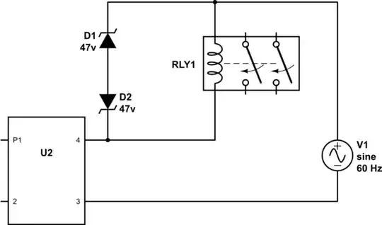
I would like to offer alternative protection idea using two anti-series zener diodes connected in parallel to the coil. The zener voltage should be selected to never conduct with normal operation, but protect from overvoltage with some safety margin. High limit for the voltage is component tolerance (I believe it was 60VDC). Low limit would be 24VAC * sqr(2) * 1.2 (for +20% safety) = 40.7V. Another considerations are zener forward voltage drop (it adds up with zener voltage), and zener voltage tolerance. In short 2 zener diodes with zener voltage of 45-54V (for 5% ZDs) and current rating that will manage the 310mA pulse rating should do. As far as thermal (power dissipation) the same goes as for the resistor from the above answer - it will depend on the number of cycles per second.

Get 2 zener diodes (I would use 47V / 2-5 watts), and connect them in series so they have opposite direction. This will make 1st diode conduct normally (with 0.7V) voltage drop while the other is going to be "zenering" (with 47V) voltage drop. In case of reverse current the two diodes simply switch their roles. The whole combination becomes a "bipolar" zener diode with 47.7V voltage drop. Below this voltage the leakage current will be very small, and above this voltage the current through diodes will steeply grow. This series combination of diodes should be considered as one new element with 2 outside connections, and simply be installed in parallel to the coil of the contactor. I'm inclined to recommend the lower voltage from the range in the original answer because of the dynamic resistance of the diodes, so the actual voltage drop will be slightly higher during current spike. The parameters for selecting the diode should be the forward voltage drop, zener voltage drop, maximum allowed pulse current, and in case of frequent switching allowed power dissipation.

Dario Dentes
  • 146
  • 1
  • 3
  • 3
    You could have edited your existing answer instead of posting a new one. You can add schematics by clicking on the schematic button in the answer editor. – JRE Dec 15 '15 at 15:09
  • Thanks JRE, I'll try that. I apologize for my clumsiness, this was my first response. – Dario Dentes Dec 15 '15 at 15:33
  • 1
    Note that the zener or RC snubber will lengthen the time required for the relay's coil to de-energize slightly. For "typical" *relay* operation, it won't be a problem... but for high-speed *solenoid* operation, it can create a "gotcha." – rdtsc Dec 15 '15 at 15:55
  • 2
    LI^2 energy in the coil is indestructible. Your choices are very high voltage and fast current drop-off or limited voltage and slower drop off. I have experimented recently with a common HVAC motor contactor (24VAC coil). It would turn on at ~12VDC, and stay on all the way down to ~0.8VDC. Maybe someone can calculate switch off delay time due to zener clamping. – Dario Dentes Dec 16 '15 at 18:46
  • 1
    Props to Mr. Dwayne Reid for pointing out Tranzorbs. Digikey has a large selection of TVS diodes (Transient Voltage Suppression). Much better than 2 zeners. TVS is a combination of 2 zeners in one case, that is optimized, and specified for this exact purpose. With AC application be sure to select only the bipolar ones. – Dario Dentes Dec 16 '15 at 18:51
  • @DarioDentes Please hit the 'edit' button to edit the answer when editing an answer – Voltage Spike Oct 26 '20 at 02:40
7

I think that using a snubber in your application is the wrong approach.

You want to design something that clamps the transient that occurs when the switch driving the contactor coil opens. A voltage clamp is the better approach.

Others have mentioned using a pair of Zener diodes connected in inverse-series. Although that is one approach, I don't like that solution because the peak power capability is so low.

Instead, I normally use either a low-voltage MOV or a bipolar Tranzorb across the contactor coil.

In your specific application, we would use a S07K35 MOV across each contactor coil. These are generally installed right at the coil terminals.

This has proven to be extremely reliable for more than 30 years in the history of my company.

Dwayne Reid
  • 23,390
  • 2
  • 35
  • 67
  • 2
    While a MOV or a TVS can shut excessive voltage, the other purpose for an RC snubber is to reduce the rate of rise (dV/dt) seen by the switch when it turns off. I have an application where I use an SSR to turn a contactor on and off and actually needed both or the contactor would not reliably turn off properly. – nsayer Feb 28 '19 at 19:07