-2

I am playing around with a clipping circuit to protect a adc on my microcontroller. I beleive the following will work, but when I simulated the circuit I saw something funky. Any ideas on why adding the diode cause the blimp seen in the image below:

With diode

Same circuit with diode removed enter image description here

schematic

simulate this circuit – Schematic created using CircuitLab

I used Olin suggestion and the blip disappeared: Circuit: enter image description here

plot with fix: enter image description here

tman
  • 533
  • 5
  • 15
  • That can't be the circuit that you simulated because the TL081's output will not swing down to 0V when the chip's negative rail is connected to 0V. Neither will the input work within typically 3V of the most negative rail i.e. 0V. Accuracy is very important here so please put the correct circuit diagram up. – Andy aka Mar 27 '15 at 13:06
  • I simulated using circuit labs...do it your self lol. I honestly assumed it was ideal with regard to the simulation. Which appears to be the case. – tman Mar 27 '15 at 13:40
  • 1
    Ah the dangers of trying something in a simulator hoping that the models are real-life perfect LOL. The glitch you see is probably the model throwing a wobbly at the input being taken beyond its operating range. Choose components, check data sheet, choose more appropriate components! – Andy aka Mar 27 '15 at 13:47
  • Yes, yes of course. I was just checking that the circuit would clip as I hoped it would. It clipped exactly how I would expect...Thanks for the help. – tman Mar 27 '15 at 13:49

1 Answers1

2

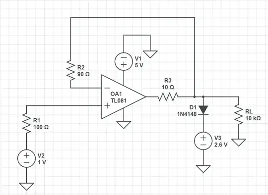
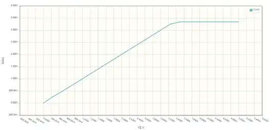
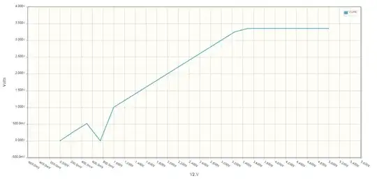
The blip in your simulation makes no sense, but then neither do parts of your circuit:

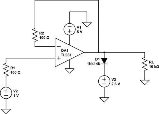
  1. R1 and R2 are pointless. What exactly do you think adding 100 Ω in series with a multi-MΩ FET input is supposed to accomplish?

  2. You are clipping against the opamp's output impedance. A 1N4148 and a theoretical voltage source can probably win against a TL081, but this is still a bad idea. Put some resistance in series with the opamp output but before the clipping diode. That way the opamp can still do what it is intended to do without violating its output current spec. Of course if you're going to do that then what's the point of the voltage follower in the first place?

  3. You are expecting a TL081 to work down to its negative supply for both the inputs and the output. That's not even close to right as the TL081 needs particularly large headroom. You need to actually read the datasheet.

A more clever way to accomplish this clipping is to put a resistor in series with the opamp output before anything else, including the feedback tap. This way, in the unclipped voltage range, the opamp will drive the left end of the resistor to whatever it takes to get the correct voltage at the right end. This compensates for small offset voltages across the resistor due to load current.

When the voltage enters the clipping range, no output the opamp can produce will cause the right end of the resistor to follow the input voltage. This will cause the opamp output to slam as high as it can go. By sizing the resistor to guarantee the opamp output current is still within spec in this case, no harm is done.

The main drawback to this approach is that the opamp will take some time to respond as the voltage goes lower out of the clipping range again. It might also ring a bit as it transitions out of having its output slammed high and back to linear operation. You might need a small cap immediately between the opamp output and its negative input to keep it stable.

Olin Lathrop
  • 310,974
  • 36
  • 428
  • 915
  • Olin, From the plots I assumed the simulation was an ideal opamp, but the blip was throwing me off. Just so I am clear on your suggestion: Split the feedback R2 into 2 resistors and move the output to between the 2 feedback resistors. Correct? – tman Mar 27 '15 at 13:45
  • I tried your suggestion and the blip magically disappeared. See updated question. – tman Mar 27 '15 at 13:57
  • @tman: You did put a reistor on the output of the opamp, but otherwise didn't listen to anything I said. – Olin Lathrop Mar 27 '15 at 14:12
  • I was curious about why the blip on a ideal simulation... it didn't make sense to me and it didn't make sense to you either, "blip in your simulation makes no sense." Question answered...Thanks – tman Mar 27 '15 at 14:16
  • For details on comment 1: see http://electronics.stackexchange.com/questions/56727/what-is-the-purpose-of-a-resistor-in-the-feedback-path-of-a-unity-gain-buffer comment 2: implemented your suggestion Comment 3: No, not at all...I thought the simulation was ideal...which it is! – tman Mar 27 '15 at 14:18