From what I have been reading, the input stages to BJT TTL logic gates are emitter terminals of transistors. As such, when the input to these gates is logic low the base-emitter junction of these input transistors will be forward biased and source current (sinking into the first stage). Further, this is the reason we find that tables similar to the following in some datasheets :
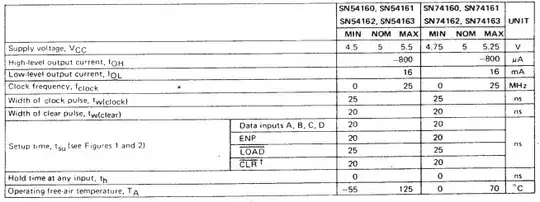
I am referring to the polarity of the current when considering polarity of logic levels. Specifically, the fact that maximum operating condition of -800uA for a logic level high is non-intuitive. Should it not be that when a gate is driven LOW the second-stage gate actually sink current into the first-stage? That is, shouldn't sinking current (logic low output state) be negative and sourcing current (logic high) be positive?
My concern is how this maximum current sink metric is related to the maximum current that may be sourced when the output of a gate is driven to a logic high state. Specifically, I had the following condition as of late:
I was recently designing a circuit that used a 74LS163 counter where the outputs were fed into some second stage logic. However, I placed some LED indicators temporarily at counter output while prototyping this circuit in order to see what the count value was at a given time. I used series resistances of 1k to severely limit the current in order to not load the output driver too much, but saw a very significant output voltage drop anyway.
Specifically, The LED I was using had a forward voltage of 2.5V. The nominal, unloaded, output of the counter was 4.5V. With the 1k series resistance we find that a mere 2mA would be drawn to drive the LED. I found that the LED indeed was dimly lit, but the output voltage dropped 1V to 3.45V despite such low current demand.
tl;dr : This led me here. The maximum current when the output is driven high is given as a maximum sinking current, but obviously the counter sources some level of current at this voltage. How do these values shown in the datasheet relate to sourcing current at logic HIGH and sinking current and LOGIC low?