I have a design that I'm working on that is to be outdoors year round, with a 1 watt solar panel trickle charging a 6 Ah li-ion battery during the day.
I expect there to be about 3 to 4 months of subzero temperatures during the winter given the local climate.
I understand that charging lithium polymer batteries when they are at sub-zero temperatures is a bad idea, since it will cause lithium plating, thereby compromising the battery's future performance.
So, when the battery is too cold to charge (below freezing), my charge controller (MCP73871) automatically stops charging the battery.
In such a case, I would like to be able to take the solar energy that isn't being used and send it to some nichrome wire i'll have wrapped around the battery. I'm thinking that some sort of configuration like this would work... any thoughts?
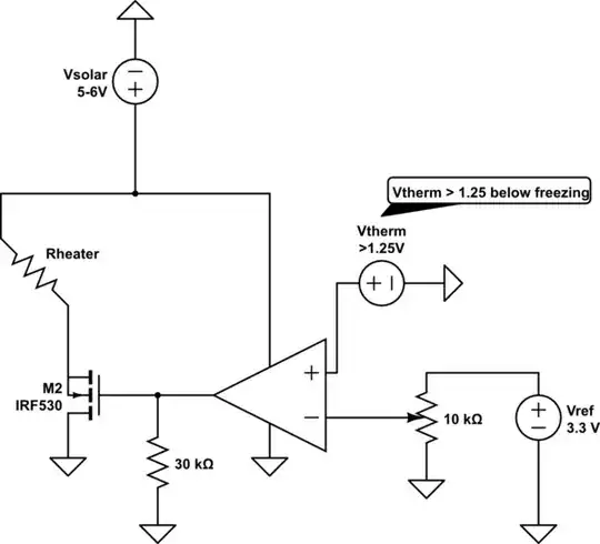
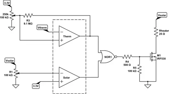
simulate this circuit – Schematic created using CircuitLab