Short answer:
Use of a SMPS (switched mode power supply) is likely to be preferable if heat generation is a genuine concern.
However, actual heat dissipation in the power supply is liable to be under 2 Watts in most cases. Whether this is significant depends on your application.
Long answer:
When attempting to provide any solution, knowing as much as possible about the actual requirement will greatly assist people who attempt to help. A poorly understood problem is liable to lead to less useful advice than would otherwise be possible.
Why do you want 22 Volts. How precise is this requirement? How much variation is acceptable either in the initial voltage or between loaded and unloaded values.
You say "... while dissipating as little heat as possible." Can you please explain why you have this requirement and how much heat you can tolerate.
eg:
You may care about the energy efficiency, or
You may want to enclose this in a space where there is very little cooling, or
- you may wish to run it in a refrigerated space where heat produced is a load on the refigeration system, or
- ... ?
Knowing the reason for the requirement is important in understanding it.
Also, stating how much heat you can tolerate may assist us providing a good answer. If you can ask a perfect question then we can provide a perfect answer ;-).
Most of the solutions so far either are based on versions of what you showed in your circuit or do not make it clear what technology is used. If minimising heat generation is genuinely important then use of a SMPS ("switch mode power supply") is probably a good idea. These can operate at in excess of 90% efficient and will automatically adjust for variations in mains voltage. At say 90% efficient and a 22V, 0.5A output, the energy lost as heat will be
Energy lost = 22V x 0.5A x (10%/90%) = 11 x 1/9 =~ 1.2 Watts.
That is a small amount of thermal energy in most contexts.
Whether it is small enough in yours depends on your requirement.
As a guide to what you can expect from a "linear" supply of the type you have shown:
Lossesof a componentare roughly proportional to the voltage drop they cause. For example, if voltage drop across diodes was 1 Volt average and Vout = 22VDC then diode losses would be about 1V/22V ~= 4.5% of ouput power. There are reasons why this simple analysis is not completely accurate, but it is good enough to get a feel for losses.
Losses are (mainly) caused by transformer, rectifier, regulator, wiring and "headroom".
- Losses in transformer and wiring are generally small enough to be ignored in this context.
- Rectifier losses are caused vy voltage rop across the diodes. Diode drop is a minimum of 0.6 V per diode and can be more like 0.8V typically and in higher current circuits than this one can be over 1 V. Use of "Schottky" technology diodes can reduce this to 0.3V to 0.5V per diode. In the circuit shown there are 2 diodes in series conducting at all times 20 you get 2 x diode drops or about 10% losses. By chaning to a centre tapped transformer you can halve this to about 5%. By changing to Schottky diodes and a centre tapped transformer you can reduce diode losses to about 2.5%. Whether this is worthwhile depends on your requirement.
"Headroom" losses are voltage drops which have to be built into the system to make it work correctly in all cases.
eg if your mains voltage variation is +/- 5% then you must allow 5% more voltage than is necessary at the transformer output when the system is running at nominal input voltage, so that it will still function correctly when voltage input falls by 5%. This extra 5% designed voltage increase is a direct loss during normal operation. - Also, if heat dissipation is absolutely crucial you may wish to allow for the +5% mains situation when calculating heat dissipation. Under 230V +5% conditions the system will dissipate +10% more energy (approximately) - 5% due to the needed 5% overdesign to allow for low voltage !, and 5% because the mains is 5% higher than usual.
The regulator will require some input to output voltage drop to function. This is part of overall "headroom". The LM317 regulator mentioned is an extremely useful IC but requires about 2V "headroom" to operate.
Data sheet: http://bit.ly/DS_LM317
This is about an additional 9% loss in this circuit (!)
A genuine LDO (low dropout) regulator can have almost zero dropout voltage if absolutely necessary.
Finally, as noted by others, the input capacitor will have some "ripple voltage" as its voltage falls when it supplied current when the transformer output drops towrds zero on each half cycle. The amount of ripple can be designed - the larger the capacitor the lower the ripple. Headroom losses due to ripple will be about 2.5% per 1 Volt peak to valley ripple. (This is half loss due to a 1V DC drop as the average value of the ripple is about half its peak to valley magnitude. Assume for now we design for 1V p-v capacitor ripple or 0.5 V average.
Adding these up we get
Rectifier + mains voltage variation allowance + regulator dropout + headroom
MJixing % losses and voltage drops as explained above.
Best case 0.3V + 5% + 0 + 0.5V = 0.8V + 5% =~ 9% =~ 1 Watt
Here, using Schottky rectifier, centre tapped transformer, 1V ripple and perfect LDO the allowance for mains variation dominates.
Typical case using circuit as shown, LM317 and 1V ripple.
Losses = 1.2V + 5% + 2V + 0.5V = 3.7V + 5% =~17% losses.
Thermally, if output = 22V x 0.5A = 11 Watt, losses would be 1.9 Watt.
So we get:
1.2W SMPS at 90%
1 W linear best case.
1.9W linear typical.
For most purposes the differences would be of low importance or even insignificant. In some cases they may be crucial.
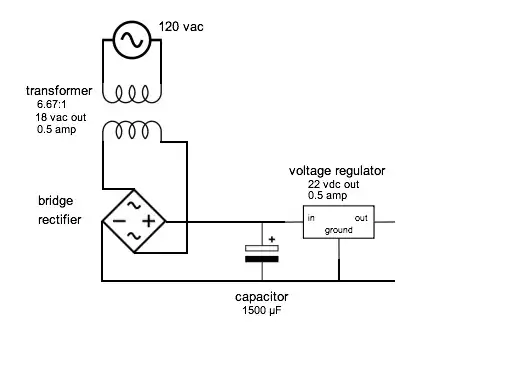
In many cases a single winding transformer, intelligently sized winding voltage, 4 diode bridge and as large a capacitor as sensibly possible (allowing a lower transformer voltage) would be adqeaute. HOWEVER it is easy to get far greater dissipation if eg the transformer woltage is not well designed. eg a 18V winding would have an RMS voltage and so a nominal rectified DC voltage of about 25.5V.
The additional (25.5-18) = 7.5V ~= 4 Watts has to be dissipated in some manner.
So, use of a smps is likely to be preferable if heat generation is a genuine convcern