4

Is there a way to build a log amplifier using vacuum tubes? I would like to have a VU meter (with the proper log response,) but do not want to use solid state components. The output would be to an IN-13 neon indicator which has a linear response between the current and the length of the light bar.

I know that I could build an opamp out of tubes and then use any of the opamp circuits available to get what I want, but I am wondering if there is an easier way to do it using fewer tubes.

I also know that I could use a magic eye tube (EM84 or similar) because they have a log response already, but the tubes are smaller and would not look as good from further away than the IN-13.

As this is for a VU meter and not for some scientific purpose or an analog computer, the response does not need to be perfectly accurate, just accurate enough to not look that much different on the output.

JRE
  • 67,678
  • 8
  • 104
  • 179
Pentium100
  • 6,550
  • 3
  • 32
  • 39
  • IN-13 has a linear response? To get log response from it you just need another circuit to do the log conversion before. – HKOB Mar 19 '15 at 06:12
  • @HKOB, hence the question - is there a way to do the conversion with vacuum tubes without building an opamp from them. – Pentium100 Mar 19 '15 at 06:23
  • If you have an exponential response on a V/I curve just send the current in and read the voltage. Voila job done. – HKOB Mar 19 '15 at 06:28
  • You will find an example of an audio amplifier using an IN13 bar graph here : http://constructions.f6fkn.com/push-pull6s33s6j/index.html – greg Mar 23 '15 at 11:23

2 Answers2

7

Certainly possible. The classical way is to overload a pentode amplifier stage and measure the way the anode current drops as the signal level increases. So the anode current is a maximum at zero signal, and progressively (but non-linearly) reduces as signal level increases.

You will find a schematic on page 5 of this manual for a precision audio test set, the (1960s) BBC Designs Department ATM/1, which was usually partnered with the TS/10 Wien bridge oscillator. Beautifully made, and a few still around when I joined thu BBC in the 1980s - though you only used it if someone else was using the EP14... I had the opportunity to buy one after they were all retired.

The relevant circuitry is V4 (rectifier), V5 and V6 on the schematic (p.5) - V6 is a barretter (??? a voltage stabiliser), providing a stable voltage (130V I think) to the screen grid. As the anode and screen grid share the cathode current, this is important to getting the law right. (V6 can probably be replaced with zener diodes, if you don't mind a little passive silicon!) V5 (CV454) is a 6BA6 in my example.

Note the adjustments R51,R52 for "zero" and "law" - there is a strict calibration procedure against known reference levels to get the law accurate enough for broadcast work. Best description of that procedure I can find online is here.

For a VU meter you will have to adjust the attack and decay time constants (R35,C15,R37) to slow the metering down - increasing R35 to about 100k may be a good start, as this is a Peak Program Meter not a slow (averaging) VU meter, designed to measure short term peaks which could overload a transmitter.

Also, as "zero" corresponds to full current and "max" to zero current, this circuit assumes you can ask the meter manufacturers (Ernest Turner) to make you a right-hand zero meter! If you can't, and don't have as eclectic a junk box as mine, the simplest solution is to mount a regular meter upside down...

Source : archive of old BBC equipment manuals and select "ATM1".

  • I'll study this in more detail when I have the time, though a bargraph that shrinks when the signal is higher would be fun. I guess I could also invert this with a tube working in the linear region (grounded cathode with the indicator as the anode load). Also, V6 looks like a neon stabilizer (vacuum tube zener), not a baretter. A baretter provides constant current, not voltage and consists of a filament. – Pentium100 Mar 19 '15 at 11:10
  • You may be right on the barretter, it's been a while! –  Mar 19 '15 at 11:13
  • Note that not all pentodes can do the job: 6BA6 is a "remote cutoff" pentode with control grid graded to produce a log relation between grid voltage and plate current. A "sharp cutoff" pentode without the graded grid is too linear. – John Doty May 08 '23 at 12:51
  • I think the V6 (and according to the schematic) is a gas filled voltage stabilizer. A "baretter" is a current stabilizing device, usually an iron wire in a hydrogen medium. (like a light bulb, but not tungsten, but iron, and not vacuum or krypton, but hydrogen at atmospheric pressure, which is an extremely good heat conductor) – Márius Bogdán May 08 '23 at 11:34
1

Not to fully answer/solve the question, but just provide some interesting information around the subject:

Tubes of course have an exponential tail, just as semiconductor FETs do.

It's probably hard to make use of, though.

Once upon a time I characterized a 6AL5, and fit this model to it:
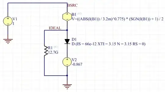
6AL5 diode SPICE model

In code:

.SUBCKT 6AL5 1 2
B2 1 IDEAL V=((ABS(I(B2)) / 3.2m)^0.775) * (SGN(I(B2)) + 1) / 2
D1 IDEAL 3 6AL5_EXP
R2 IDEAL 2 12.7G
V2 3 2 -0.867
.ENDS

.MODEL 6AL5_EXP D (IS=66e-12 XTI=3.15 N=3.15 RS=0)

Note that a SPICE diode is used to express the exponential tail, which is apparent at low currents. (The N=3.15 implies either significant non-ideality (analogous to the semiconductor case), or a cathode temperature several times room temp, which seems reasonable enough -- room temp is ~300 K while the oxide-coated cathode is ~900 K.)

Note also the negative source: there is, in fact, current flow at zero voltage, and a small amount of power available (nanowatts) from a heated diode. It's a thermionic generator, of bafflingly low efficiency, but it is indeed thermodynamically realistic.

At higher currents (~uA?), the Child-Langmuir law takes over; here, not quite the ideal 3/2 power (or its reciprocal rather, for voltage in terms of current), but a little off, presumably due to material and geometry factors.

Since the exponential region is so small, I doubt that much use could be made of this, but perhaps a couple decades would be enough for some purposes.

More practical would be the same detailed analysis on the transfer function (of a triode or pentode, etc.), but which will I think quickly be dominated by leakage currents in most types. A more reliable solution probably involves a carefully contrived transfer function (see the other answer's use of a remote-cutoff pentode*), quirks of the screen-plate transfer function in a tetrode or pentode, or a multi-parameter curve fit (i.e., a dozen trimpots that all interact..).

*Carefully contrived, in the sense that, remote-cutoff types were contrived by way of varying the spacing of the grid wires; their characteristic isn't a direct result of intrinsic device properties (physics or geometry), in contrast to the diode's exponential tail which is.

Tim Williams
  • 22,874
  • 1
  • 20
  • 71