I have a simple circuit that amplifies the output of an electret to drive a simple volume visualisation with an array of LEDs.
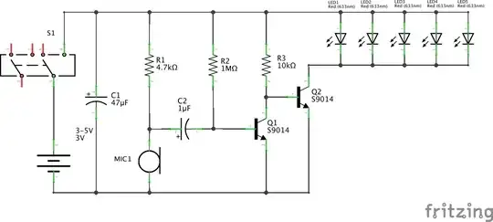
I didn't design the circuit (though I did build it - works fine), but ignoring whether this is a good circuit or not, I would really like to understand and be able to calculate precisely what is happening in the interaction of the electret and Q1.
Specifically I think this boils down to being able to calculate unexcited, nominal and peak AC signal across C2, and the effect this has on the current to the base of Q1.
Here's what I've got so far:
The Unexcited State
This is quite straight-forward. C2 is effectively open circuit, so Q1 is purely current-biased through R2, enough to have it on in the linear region. This grounds the base of Q2 and so LEDs are off.
The transistors used here are S9014 NPNs. From the datasheet, Vbe when on is 0.7V and typical beta(β) is 280. So:
- Ic(sat) = Vcc / R3 = 3/10kΩ = 0.3mA
- Ib(sat) = Ic/β = 0.3mA/280 = 1.07μA
- Ib(actual) = (Vcc-0.7)/1MΩ = (3-0.7)/10^6 = 2.3μA
The operating curve for Q1 is along the line intersecting Vce=0/Ic=0.3mA and Vce=3V/Ic=0. Considering static characteristic chart in the S9014 datasheet, this line is in the unreadably small left corner of the linear region.
So I think that establishes Q1 is on in the linear region when no input from the electret.
Nominal Signal "loud and close" (94 dB SPL)
So now I get to the core of the question - how to factor in the electret signal?
I'm using an electret similar to CMA-4544PF-W. It is biased through R1. From the datasheet I find typical sensitivity of -44dB for reference 1V/Pa at 1kHz and calculate the transfer factor thus:
- Transfer factor = 10^(Sensitivity/20) = 10^(-44/20) = 6.3mV/Pa
Now this is where I start to get lost. I think this means the amplitude of the signal will be 6.3mV: so C2 removes the DC offset and I'll have a 6.3mV alternating signal passing to the amplifier stage.
In practice, I believe the effect of this is to suck current from the base of Q1 on the down cycle, effectively trying to turn Q1 off and allowing Q2 to turn on in proportion (and vice versa on the up cycle).
If that is what is going on, I'm thinking I should be able to calculate at least the limits of Q1 operation with this signal. Specifically, how low/high would be the Q1 base current, and hence be able to calculate the limits of Q2/LED operation.
Does that sound correct? If so, what's the best way to calculate it?
Peak Signal?
I'm thinking I should also be interested in the absolute limits of the electret. i.e. what is the peak signal it can spike? Or is this in fact the sensitivity I'm already looking at?
PS: if anyone can suggest a good reference for methods of modelling an electret in a circuit, I'd greatly appreciate it! I searched but didn't come up with much. You can probably tell I'm still learning how to figure this out.