4

I'm a complete electronics newbie.

I have a auto fish feeder that takes 2 AA (1.5V) batteries. After changing the batteries quite often I got curious to find out if the feeder can be modified to run using the electricity at home. Some research led me to find these:

  • The AC current has to be converted to DC
  • An adapter is needed that converts 220V AC to 3V DC
  • I need a multimeter

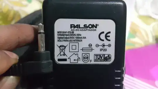
So I looked around and found an adapter at home which says: Output:3VDC 1000mA 3VA. I actually have no clue what that means but I'm guessing that it will output the 3V required to run the auto feeder.

Bought a multimeter and used it to measure the output of the adapter. I was expecting to see 3.00.

Nope. I'm getting a reading of 6.46 every time.

So this is my question - is it OK to go ahead and wire the adapter to the fish feeder despite the higher reading? Will everything magically work or something is sure to blow up? Will adding some register help? I would've gone ahead to find out if the feeder was available in my Country. I imported it from the US so I don't want to mess it up.

Could you guys please give me advice on how I can accomplish what I'm trying to do? I'm totally ok to start from scratch.

EDIT: As for the adapter, it's from an electric shaver and this is how it looks: the adapter

Jonas Stein
  • 410
  • 3
  • 14
Yeti
  • 143
  • 6

5 Answers5

9

Judging from the picture that you posted:

DC Adapter

You have an unregulated DC adapter. See this link for some more details.

In simple terms, the amount of voltage that your adapter puts out goes down as the amount of current draw goes up. In your case, the adapter is rated for 3 VDC at 1000 mA, so it will put out:

  • 3 V when you draw 1000 mA
  • < 3 V when you draw more than 1000 mA
  • 3 V when you draw less than 1000 mA (as you've measured, 6.46 V at 0 mA)

Since I don't know anything about your fish feeder, I don't know how much current it'll take or how much voltage is safe to put on it. It might work. It might not. If you can get your hands on a regulated 3 V adapter, you and your fish would be much happier.

Greg d'Eon
  • 3,807
  • 4
  • 24
  • 50
  • How can I calculate how much mA is being used by the feeder? Can it be done using the multimeter? – Yeti Mar 06 '15 at 14:24
  • 1
    You might be able to use your multimeter to measure the current coming out of the batteries when they're connected to the feeder. There should be lots of tutorials online on how to do this. Here is a decent one for beginners: http://www.allaboutcircuits.com/vol_6/chpt_2/4.html (replace the lamp with your feeder) – Greg d'Eon Mar 06 '15 at 14:28
  • Tried this and got an average reading of 60(mA?) when the motor runs (for about 10 seconds). For a second, when the motor starts the number go up to 90. So how can I use this data? Just for the kicks I tried using 3 batteries and the reading was at 79 constantly and the motor completed running in 6 seconds. Does this in anyway harm the device? – Yeti Mar 06 '15 at 15:13
  • I really don't know the specifics of what happens when you put too much voltage on a motor. It might work perfectly, it might work sometimes, or it might work never again. If your feeder is only drawing < 100 mA, I don't think I would trust this adapter with it. I think Spehro's answer sounds like a better plan. – Greg d'Eon Mar 06 '15 at 15:20
  • 2
    1000mA would be an extremely high load for a AA alkaline battery, so knowing that's the power source, it's pretty easy to infer that this DC adapter is a sufficient replacement in terms of current rating. – Phil Frost Mar 06 '15 at 15:25
  • @PhilFrost I'm worried for the opposite effect. I've recently serviced a similar device and it had a bare 3v motor fed by the two batteries. I worry for the motor windings in case it's heavily loaded or even worse forced to stop (not able to rotate). The PSU will be able to provide more power for a longer time and may damage/overheat the motor. Maybe a small resistor in series with the motor (a few ohms) would be a wise move. – alexan_e Mar 06 '15 at 21:01
  • 3
    @PhilFrost I would argue the exact opposite, using your same logic: since we know the feeder will use <1000mA, and since we know the power supply is a linear/unregulated supply (since he tested 6.47V @ no load), it's pretty easy to infer that this adapter will provide excessive voltage to the feeder, quite possibly damaging it. – Doktor J Mar 07 '15 at 02:43
  • As I've commented on another answer below I hooked up the adapter to the feeder. It ran at 90mA and the motor rotated twice as fast (in half the time). Now I hear a clicking sound when motor runs. I've concluded that the motor should run at no more 60mA (reading on 2 AA batteries). I'm still trying to figure out how to achieve this using resistors. – Yeti Mar 07 '15 at 04:25
  • @DoktorJ *in terms of current rating*. Dealing with excess voltage is trivial. – Phil Frost Mar 07 '15 at 12:56
  • 1
    I got hold of a regulated 3V adapter. It's outputs exactly 3 volts, so the problem is solved. I tried using resistors in the previous adaptor but figured out it wasn't worth the trouble. – Yeti Mar 12 '15 at 14:22
6

You can add a regulator, but since good engineers not only solve problems but save money, I'll suggest a cheaper solution.

Put a resistor in parallel with the fish feeder. You will probably find that if you give the wall wart just a little bit of load, the voltage will drop to something more reasonable. It still won't be well regulated, but I doubt your fish feeder will care.

I'd start with a 2.2kΩ resistor, which by Ohm's law, would draw:

$$ {3\:\mathrm V \over 2.2\:\mathrm{k\Omega}} = 1.36\:\mathrm{mA} $$

and consume energy at a rate of:

$$ 1.36\:\mathrm{mA} \cdot 3\:\mathrm V = 4\:\mathrm{mW} $$

That's of course based on the assumption that with this added load, the adapter will supply its rated 3V.

So try a resistor, and if the voltage is still to high, try a slightly smaller resistor. Be sure that the power doesn't exceed the resistor's capabilities, 1/4 W for the most common variety. And make sure you aren't drawing an appreciable fraction of the supply's rated 1000 mA through the resistor, otherwise there will none done left for the fish feeder.

You will probably find that you are nowhere near these limits before the voltage drops. You don't have to drop it all the way to 3V, either. 4V is probably just fine.

In fact if you really wanted to save money, you might be able to put the unregulated 6.46V into the fish feeder. I'd say you should read the fish feeder's datasheet to make sure you aren't exceeding its specifications, but I'm guessing you don't have that datasheet.

Phil Frost
  • 56,804
  • 17
  • 141
  • 262
  • 1
    Good answer; +1. FYI, 36 ohms is the point where V^2 / R will be greater than 1/4 W - but as Phil says, you probably won't be near that point just to make it work. – Greg d'Eon Mar 06 '15 at 16:28
  • I don't have the registor yet. I went ahead and connected the feeder to the adapter anyways. The reading was at 90mA constant and motor rotated in 5 seconds. This is similar to when I used 3 AA batteries. The problem is that now I hear a clicking sound when the motor rotates (whoops!). So now I'm sure that the feeder must only operate at 60mA. Anything more than that rotates the motor too fast and feeding is incorrect. I'll try to get hold of the registor. Is there anything else I need to do/buy? – Yeti Mar 07 '15 at 02:39
  • @Yeti What voltage do you measure when the feeder is connected? – user253751 Mar 07 '15 at 06:08
  • @immibis when the motor is running the voltage is 5.4v. When I complete the circuit using the multimeter the voltage shown is 3.9v. – Yeti Mar 07 '15 at 08:12
  • @Yeti I don't know what you mean by "when I complete the circuit using the multimeter". – user253751 Mar 07 '15 at 08:20
  • @Yeti but from the first measurement (5.4V with the motor running) it looks like the power brick simply won't output the right voltage unless it's supplying about 1000mA. (Which is normal for a simple, not-so-modern, unregulated power brick). Which means if you go with a resistor in parallel, you'd probably need it to waste a fair bit of current to keep the voltage down. – user253751 Mar 07 '15 at 08:22
  • @immibis looks like the best solution here is to go get a regulated adaptor (which I doubt I'll find in my country). I'll try using a 2.2kΩ resistor and see how it goes. – Yeti Mar 07 '15 at 08:25
  • Let us [continue this discussion in chat](http://chat.stackexchange.com/rooms/21729/discussion-between-immibis-and-yeti). – user253751 Mar 07 '15 at 08:26
5

Please keep in mind, that the fish feeder may have been designed to run on batteries only as it may assume battery internal resistance. I may not be the case, but if it is you will blow the shit out of it when you connect it to DC adapter, even if it's just 3V.

Cano64
  • 807
  • 1
  • 8
  • 15
  • Good point - certainly applies to torch lightbulbs. In this case, the OP has already tried (without our permission) to operate it with three batteries, and it survived! – tomnexus Mar 06 '15 at 18:58
  • To test, I hooked up the feeder to the 3v adapter and fortunately nothing blew up. The motor however ran twice as fast (at 90mA) which lead to unreliable feeding. Also now I hear a clicking sound when the motor rotates. On battery the feeder runs at 60mA, which I now somehow need to reproduce using resistors or something. Advice? – Yeti Mar 07 '15 at 02:47
4

Since this is an engineering forum, I'll say that you could add an LDO regulator to your existing adapter- using a part such as the Diodes Incorporated AP1186T5-33L-U. It should have a small heat sink to be safe (1 square inch of copper is probably enough). That will take care of the variation in your adapter output without dropping too much voltage at full current. They're $1.58 each in singles. This part is on the way out, but for a one-off it's not a problem.

It needs a few electrolytic capacitors (the can type) in addition to the chip (3 x 100uF will work).

Personally, I'd probably just buy a switching adapter (make sure they have genuine safety-agency approval or listing markings.. not just a generic PRC "CE" mark that has no real value)-- some of the ones on eBay etc. are criminally bad. That will use less vampire power so your electric bills are less (assuming 24/7 operation this can be a factor- the type of adapter you show typically runs noticeably warm and you're paying for that wasted heat).

Spehro Pefhany
  • 376,485
  • 21
  • 320
  • 842
1

Your meter probably has the ability to measure resistance. You can connect it across the heater and read some number of ohms. Say you get 30 ohms. The current at 3V is then 3/30=0.1A=100 mA. As long as the resistance is greater than 3 ohms you will be within the 1000 mA current rating of your adapter. The power of the heater is V^2/R=9/R Watts. On the heater package you may find a heater power, which would also let you calculate R. I suspect that the 6.46 Volts you measured was open circuit, without the heater connected. It will be lower with the heater connected.

Ross Millikan
  • 260
  • 1
  • 7
  • I doubt he would be able to get an accurate measurement this way - if it was a heater, then the temperature it is at is likely to have an effect on the resistance - but in this case, it's even worse - it's an electric motor, which will have inductance, and depend on which position it is in as far as what resistance it has. – user2813274 Mar 07 '15 at 15:33