-2

I am in the quest to build a cheap bench power supply, i have successfully designed, built and tested the entire voltage circuitry.

The device includes a graphic LCD screen that displays the voltage output. I am in the process of designing the variable amperage part of the circuitry and i don't quite understand something.

I want to add measurement of the amp limit like all bench top power supply have, but i am not quite sure how to measure that. Is there a chip inside it that approximates the value and displays it depending on the position of the knob?

Or is there a way to measure it using a multimeter with no load on it?
silviussa
  • 19
  • 1
  • 3

1 Answers1

0

Limiting the current output is not the same as just measuring it, although to limit you'll need some form of measurement/feedback anyway. I suggest you look into using a current shunt resistor on the output of your custom power supply you are designing.

Texas Instruments has a great range of current shunt monitors (purpose-built op-amps which are really handy for linear current measurement) in their INA series, i've used the INA136 with great success in my own projects.

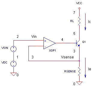
You should check out how to implement your own feedback based current limiting using an op-amp and a FET, as shown here and the picture below is from that site:

enter image description here

The operation of the current limiter opamp-FET combination is unrelated/separate from the current measurement, although nothing stops you from using the same RSENSE for a current shunt monitor IC like I mentioned before!

This way you can tune the set-point for the current source/limiter using a potentiometer/knob just like a bench power supply does it.

KyranF
  • 6,248
  • 16
  • 25
  • Thank you very much for your reply! I guess i didn't word my question correctly, i do know, at least at a basic level how to limit the current. I found this example interesting, using a linear LM723 as the easiest approach [link](http://electronics-diy.com/30v-10a-variable-bench-power-supply.php). I was mostly interested on the measuring part, as far as i understand it, you're suggesting using an opamp and a resistor in line, and measure the current delivered to that resistor, right? wouldn't the resistance level affect the reading? – silviussa Feb 27 '15 at 04:10
  • I don't quite understand what is the use of those transistors in the upper right part tho – silviussa Feb 27 '15 at 04:21
  • Yes, use an opamp, or a proper purpose built IC like a current shunt monitor (essentially an opamp but with more fancy stuff added) with a resistor "in line" with the load. The current delivered to the load has to go through the resistor first. Current though a resistor creates a voltage difference, which is amplified by the shunt monitor IC/Opamp. The resistor value DOES affect the reading, and they are often very low, like 10 milliohms with 1% precision or better. The current monitor ICs have nice gain adjustment for dealing with low resistance shunts. – KyranF Feb 27 '15 at 06:10
  • @SilviuStroe the transistor shown in the image on the right (above the resistor) is usually a FET, and is used to linearly limit the current delivered to the load. It's effect is similar to a voltage controlled resistor, and once you hit the current limit, it very quickly turns on. This drops voltage though, as you see in bench power supplies when there is a short/you reach maximum current output and the voltage fails to regulate correctly. – KyranF Feb 27 '15 at 06:11
  • Thank you again for your answer, very useful information, i will search for a purpose built IC like the INA136 or the INA223. About the transistor question, i was referring to the link i provided, sorry for the misunderstanding. In all diagrams I see, there are loads connected to the supply, but i want to measure the constant current being delivered by the supply even at idle. Exactly like professional supplies do. I can imagine that it would work for that purpose as well, just have to shift the circuit a little bit. – silviussa Feb 27 '15 at 06:38
  • @SilviuStroe if the industrial supplies deliver a constant current without a load attached, it means they shunt it or otherwise waste it? That's the only explanation I can come up with as to where the energy is being consumed. Perhaps it creates a low "power" low voltage short circuit with the required constant current until the load is attached? – KyranF Feb 27 '15 at 06:45