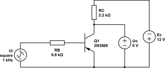
I've designed the following amplifier circuit to amplify a DAC signal (sorry for the non-standard opamp symbol):
It's a power amplifier which amplifies a microcontroller DAC signal 0-5VDC and very low current, to 0-22VDC, with current draw up to 2.5A. That would be a gain of approximately 4.4. The input voltage only changes several dozen times per second. Let's say 100Hz to be safe. But it needs to operate over a wide range of (fluctuating) loads. Load could be from 5 ohms to 5 megaohms for example.
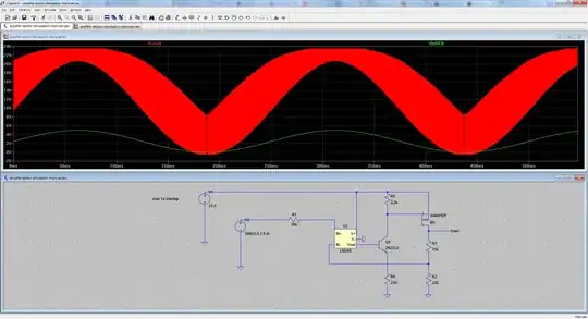
It simulates just fine with the default PMOS component, which I suppose is an ideal FET. But when I add all "real" components in, I get oscillation occuring. How might I stabilize this? How accurate is a simulation in such things compared to a real circuit?
Is there anything else that looks like it could be an issue in this circuit, for example part choice, voltages, etc?
LTspice v4.22s schematic download: enter link description here
EDIT:
I've made some changes based on mostly trial and error, but educated by the replies below. I managed to remove the oscillation fairly quickly, but, I have no idea why adding a capacitor in each of these locations solved the problem. I needed both of them, and I needed to fine tune their values a bit.

This is for a power supply so the new voltage spike at the beginning is rather disastrous. Here is a closeup of it now with a resistor added in series with C1 to stop it oscillating: