1

I'm trying to build a battery capacity tester for Li-ion batteries.
I made this schematic using Arduino:
enter image description here

While bush button is not triggered arduino only shows battery voltage on Serial & when button is triggered it turns on the MOSFET and starts the test.
My problem is while MOSFET is off the battery voltage that arduino reads is battery's 100% voltage (e.g. 3.97v)
But when MOSFET turns on the battery voltage drops to a lower value (e.g. 3.21v for that initial 3.97v) !
And when the test is finished (arduino reads 2.7v) and it turns off the MOSFET that dropped voltage comes back! and 2.7v becomes 3.5 !!
for different amount of load resistor this drop is different (larger resistor ,less drop!)

Why this happens? am I doing something wrong?

Ariyan
  • 301
  • 5
  • 14
  • 1
    A battery (with its serial resistance) can only provide so much current/energy so for a specific load to match it (ohms law and stuff) the voltage must be lower. – PlasmaHH Feb 25 '15 at 11:40
  • @PlasmaHH: so, i need to take a lower cutoff voltage level? or what? – Ariyan Feb 25 '15 at 11:44
  • 1
    What were you expecting would happen? Note also that the IRF640 is an inappropriate part if you want consistent results as Rds(on) is not well defined with logic level drive. – Spehro Pefhany Feb 25 '15 at 11:47
  • @SpehroPefhany: I want to empty a full changed battery up to its lower limit to measure its capacity (mAh); datasheet says Rds(on) is 0.18 ; what type of fet is appropriate? – Ariyan Feb 25 '15 at 11:52
  • I see no ground connection between Arduino and battery circuit. If the latter is floating, voltage readings at the former will be meaningless. –  Feb 25 '15 at 11:54
  • @BrianDrummond: oh, I missed it in schematic, there is a connection between `GND` and battery's negative lead – Ariyan Feb 25 '15 at 11:57
  • 2
    @4r1y4n The datasheet I have says 0.15\$\Omega\$ **at Tj = 25°C AND Vgs = 10V**. For this application you should have a MOSFET specified with Vgs = your microcontroller output voltage or lower (eg. 4.5V for a 5V micro). – Spehro Pefhany Feb 25 '15 at 11:57
  • @SpehroPefhany: thank you very much about mosfet, and I think i need to switch the mosfet off for taking samples that i didn't currently; I will change the mosfet and test again with switching off/on again; Thanks – Ariyan Feb 25 '15 at 12:01
  • @4r1y4n Your battery manufacturer's info should tell you the conditions under which to measure the battery voltage for battery protection. If you are using a dubious source of batteries, you can use information from a reputable maker. – Spehro Pefhany Feb 25 '15 at 12:25

3 Answers3

3

A battery has some internal resistance that for Li-ion batteries is usually in the 0.15 \$\Omega\$ region when fresh.

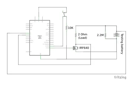
As you should know from Ohm's Law, \$V = I \times R\$ so if you put a load on the battery this will cause a current to drain from the battery and this will cause, depending on the current, a small voltage drop over the battery's internal resistance as it would on any normal resistor in a circuit. This can be explained visually like so:

schematic

simulate this circuit – Schematic created using CircuitLab

As the battery gets used and 'ages' this internal resistance increases so the voltage drop over it will also increase for a constant current. The 'open-circuit' voltage of the battery will always be more or less the initial voltage as the 'load' will be near infinity so all the voltage drop will be over this air-gap between the batteries two terminals.
As you mentioned the drop in voltage is less with a larger load, this is because the current draw will be less and hence the drop over the internal resistance will also be less.

You should look into a constant current source using a low voltage op-amp (I did something similar to this a couple of months a go and ran into the same issue - hence that question) and you'll be able to work out the mAh easily enough as the current should be more or less constant and you'll know the time taken for the voltage to fall.

Hopefully this helps and answers your question - it is expected that a voltage drop will be seen when applying a load to a battery.

MrPhooky
  • 2,168
  • 8
  • 24
  • 55
1

The normal procedure for measuring battery capacity is to discharge at a constant current until the battery voltage drops to some endpoint voltage. The constant current and endpoint voltage should be specified in the battery datasheet. It is normal for the battery voltage to recover when you remove the load. That is, the open circuit voltage will be higher than the voltage under load. But the voltage under load is what is used for capacity measurement.

Your circuit is not a constant current circuit, so you may get slightly different results compared to the datashseet. Your circuit (if you fix the mosfet problem Spehro mentioned) could still be useful for comparing cells to each other, but not for comparing to battery specifications.

Make sure that the discharge current does not exceed recommended maximum for the given cell. For example, if you are testing small cells (less than 2 Ah), your 2 Ohm load could discharge the cell very fast, resulting in abusive conditions for the cell.

user57037
  • 28,915
  • 1
  • 28
  • 81
1

A simple workaround is to measure voltage under load and without load. So you can calculate the change in internal resistance. Regarding the capacity of the battery, it is important to know under what discharge conditions this capacity is calculated. Very often this is a 20 hour discharge with low current - conditions too favorable for good results.

Peter MP
  • 403
  • 4
  • 10
  • Welcome to EE.SE. "*So you can calculate the change in internal resistance.*" The internal resistance will remain pretty much the same. What will change is the internal voltage drop and this will be zero at zero current. – Transistor Feb 17 '20 at 23:52