3

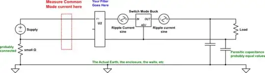
I have a setup with a DC/DC converter like in the figure below. I need to minimize common mode current on the supply input.

There are no other connections besides Vsupply + and - and Rload + and -.

setup

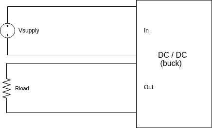
I'm in doubt whether a CM choke will help reducing the CM current. And how would it need to be connected to the grounds of the DC/DC and the load. I've drawn to ways to connect it, but I'm not happy with either one.

schematic

simulate this circuit – Schematic created using CircuitLab In this circuit the Supply is separated from the buck and the load with a CM choke. But because the CM choke is in the supply GND - load GND path, this increases the transfer impedance. (The choke is depicted by L1 and L2)

schematic

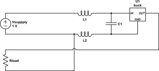
simulate this circuit With this connection, the transfer impedance issue is solved, but now the CM choke is partly in the feedback loop.

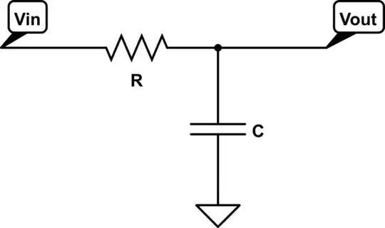
Can I use a CM choke to reduce CM currents to the supply? How? Should I use a different filter?

MrPiet
  • 31
  • 1
  • 3

1 Answers1

4

I assume you refer to an EMC problem, high frequency currents.

A common-mode filter has no C1, that's for differential mode.

EMI is always solved by going way back to the basics. In a circuit as simple as yours, there is no common-mode current possible unless you consider the effect of the outside world, and antennas.

You think you have this:

schematic

simulate this circuit – Schematic created using CircuitLab

But in fact you have this:

schematic

simulate this circuit The parasitic capacitance(s), ground connections, and even worse, antenna effects, are the only way it can generate common-mode currents.

Now you can start to think about what would help. Inductance in series definitely helps. Capacitance... but to what? Any asymmetry in the circuit will convert differential mode to common mode currents. Best to suppress the DM currents first, with series inductors (only on the +V side) and parallel capacitors.

If you must, connect the sense pin of the regulator to the far side of the filter, but it's unlikely that the regulator bandwidth is anywhere near the sort of frequencies you are failing on. So rather let the regulator do its job, and then filter and suppress those high frequencies. The filter impedance at high frequency is very low anyway, so the regulation will be good there.

So to answer your questions directly:

  • You can use the CM filter you have, as it has some series inductance
  • the second circuit looks like a bad idea, you don't want to have anything inside the buck converter's architecture. High frequency currents there!
  • Your third circuit looks a bit scary too, you need the inductance in series
  • You need to think about where you can put the parallel capacitors too.
tomnexus
  • 7,617
  • 3
  • 19
  • 35
  • I'm indeed referring to EMC. The sources of the EMI are the switching of the buck converter. Besides the Supply - and the Buck GND (which are drawn in the schematics), there is no ground. How should I connect the CM filter? – MrPiet Feb 24 '15 at 12:09
  • Just re-written my answer after realising it was too simplistic. Hope it makes more sense now. – tomnexus Feb 24 '15 at 12:11