2

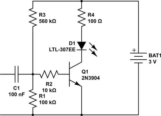
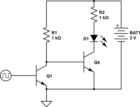
I recently built a circuit using a 2N3904 BJT transistor with the hopes that when connected to a headphone jack, it would light a LED whenever an audio signal was passed through. However, I found that this only worked when I put my devices to full volume (or at least > 80%). Trying a Darlington transistor setup didn't help. I need this LED to activate at much lower volumes (this is for a research project in which I need a visual indication that a sound is playing, often at 50% volume). My proposed solution:

Add a 1.5V battery and resistor to the Audio line in before the transistor base so the battery will amplify the baseline voltage enough that it will trigger at lower volumes. Then I could just use the appropriate resistor to adjust the voltage amplification of the signal for different sounds I'm using.

Before I try this, I thought I'd post on here and get some second opinions. My two questions are:

-Will this work to amplify the voltage of the audio signal as I'm intending?

-If so, will I run into any risk of damaging any headphone jacks which are plugged into this?

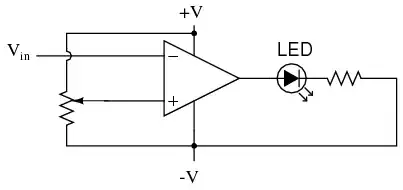
On the image, the ground and empty negative terminal of the battery at the top are connected to the ground and Left audio channel of the headphone cable, respectively. Any advice is greatly appreciated!

Schematic

This is similar to the question posted here: How can I effectively reduce the voltage needed to activate a transistor? But since I'm a beginner, I'm looking for easier ways to amplify the signal. This "just has to work" without being fancy.

RTbecard
  • 202
  • 3
  • 8
  • 2
    That seems, well, bad. – Passerby Feb 18 '15 at 17:08
  • So... Currently you have the same circuit but minus the 1.5V battery and it doesn't work? I agree with Passerby it sounds like a bad idea. – I. Wolfe Feb 18 '15 at 17:17
  • possible duplicate of [Power LED from headphone jack](http://electronics.stackexchange.com/questions/26785/power-led-from-headphone-jack) – I. Wolfe Feb 18 '15 at 17:36
  • I still can't understand why you set your circuit up the way you did. Would make more sense to switch the LED to gnd using an NPN as in http://electronics.stackexchange.com/questions/26785/power-led-from-headphone-jack answer. The way your circuit is set up you have ground tied to the anode of the LED which makes no sense. – I. Wolfe Feb 18 '15 at 17:38
  • 2
    This very likely won't work, and it may damage devices that you plug it into. The behaviour is likely to be dependent on exactly how the headphone output circuitry is arranged. If the output has very low impedance at DC, your battery could drive quite a large current through your headphone output, damaging it. – Chris Johnson Feb 18 '15 at 17:41
  • I do have some solutions but it will take me a few hours. Basically you need an op amp of some sort, or two high gain silicon transistors. – Passerby Feb 18 '15 at 17:49
  • Thanks for the replies! I was worrying that this was probably a stupid idea! My current circuit is the same as illustrated above, but just minus the 1.5V battery and resistor. This does work… but only at very high volumes. Passerby: I've seen some solutions suggesting op-amps are relevant to this situation… but as can be seen here, my electronics knowledge is as amateur as it gets. If you could provide an example solution with an op-amp for me, I'd love it! I just have no idea what specs I should be looking for in an op-amp. – RTbecard Feb 18 '15 at 18:28

3 Answers3

3

Here is a solution that minimizes the input threshold voltage as battery voltage changes:

schematic

simulate this circuit – Schematic created using CircuitLab

Adjust R2 to control sensitivity to low-level signals. Adjust R5 to control sensitivity to high-level signals.

Dwayne Reid
  • 23,390
  • 2
  • 35
  • 67
  • This seems to put only 2mA through the led, which might not be enough for the LED shown here, but there are 2mA LEDs. Trying to get more mA by lowering R4 does run into problems when the input signal is varied as the current through the LED won't be that constant (for 20mA at 1.5V peaks I get only 5mA at 0.5V peaks.) – Fizz Sep 11 '15 at 12:26
2

Edit: Actually, I found out the answer I posted is already given in the question you rejected as "too complicated". I ask you to reconsider that judgement, as anything involving operational amplifiers (suggestions also found in that question) will be even more complicated.


While the commentors are right that your circuit is a really bad idea in practice, your thoughts that lead you to the that circuit are actually quite good. You notice correctly that the voltage you obtain at typical volumes is too low to turn on the transistor (you need around 0.6V to get a significant effect). Using a darlington transistor doesn't help, as you experienced, because you need even more voltage to turn on a darlington transistor, but you can get away with a lot lower current. You problem is that your voltage is too low, not that your supply can't deliver enough current, so forget about darlingtons.

Increasing the "baseline voltage" as you call it, is exactly the way to go. Electronics people often call this process "adjusting the DC bias" of a transistor amplifier. It can be done quite easily on your circuit without adding a dangerous low-impedance power source like a battery. Let's work on your circuit. First, add a current limiting resistor into the LED circuit and put the LED on the other side of the transistor. It makes no difference in your circuit as it is now, but it will make soon:

schematic

simulate this circuit – Schematic created using CircuitLab

You can fix your problem, as you correctly identified, by providing DC bias (a baseline voltage) to the transistor base. But you should not force a DC voltage into the headphone jack, so you need a capacitor for DC decoupling. This capacitor should pass the AC music signal, but block the DC required to bias the transistor. With the circuit as drawn, you can get the required DC bias (around 0.45V) from the battery using a voltage divider like this:

schematic

simulate this circuit

Michael Karcher
  • 2,284
  • 10
  • 19
  • Great! Thanks for the really clear and detailed explanation! It'll take me a day or so to get the extra components I need to finish this, but I'll try this out asap! – RTbecard Feb 19 '15 at 08:09
  • 1
    The circuit provided in the answer by Dwaine Reid is similar to mine, but provides way better stability of the threshould to turn on the LED when the battery voltage goes down as the battery gets depleted. That circuit uses the turn-on-voltage of a second transistor as reference for biasing instead of just a fraction of the battery voltage as my circuit does. – Michael Karcher Feb 19 '15 at 22:09
2

Few simple options. Germanium Transistors would be better because of the lower VBE voltage drop of ~0.2 instead of Silicon Transistor drop of ~0.6. Resistor values would vary, you gotta play with them.

Two NPN transistors, one as a simple switch, the other providing the current gain. Inverted, so led turns off as audio gets louder/sound plays.

schematic

simulate this circuit – Schematic created using CircuitLab

Non inverted, with 1 NPN and 1 PNP. I am not very sure if this is accurate or not (never very good with PNP logic).

schematic

simulate this circuit

Simple Opamp circuit. Look for any common battery 3V powered op amp. Nothing special. It provides plenty of gain.
enter image description here

Finally, look for dedicated ICs like the LM3914/15/16, which provide led bar graphs (VU meter), essentially designed to light leds to sound. (It's basically a bunch of the opamp circuit above, in parallel).

enter image description here

Passerby
  • 72,580
  • 7
  • 90
  • 202
  • Honestly, these are all about the same price btw. You can get a LM3915 kit for under five bucks on ebay. – Passerby Feb 20 '15 at 01:10