I know that when the frequency is 0, the voltage will be pure DC. But in DSP and Digital Communication, I have seen mentioning of negative frequencies which I dont quite understand. For example, like \$ -f_{0}\$ to \$ f_{0}\$ frequency range. How could frequency become negative?
Asked
Active
Viewed 6,216 times
33
-
9Frequency is kind of a modular concept. When talking about negative frequencies it's not really referring to the rate of change anymore (that can be thought of as the absolute value) but often a direction is implied as a result of the sign. So for example, a wheel spinning backwards might have a negative number of revolutions per second, but the wheel is spinning at the same "frequency" as if it were going forward. Not sure if that analogy would hold for everything since I'm hardly a DSP expert, but I think it's a good way to think about it. – NickHalden Jun 17 '11 at 05:28
-
1That might be important in practice when you have more than one phase, for example for motors. – starblue Jun 17 '11 at 07:52
-
http://dsp.stackexchange.com/questions/431/what-is-the-physical-significance-of-negative-frequencies – endolith Oct 18 '11 at 00:57
3 Answers
31
The derivation of
\$cos(\omega t) = \frac{1}{2} \left(e^{j\omega t} + e^{-j\omega t}\right)\$
is all very nice and such (thanks, Mark), but it's not very intuitive.
A sine can be presented in the complex plane as a rotating vector:
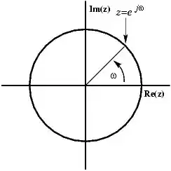
You can see how the vector consists of a real and an imaginary part. But what you see when you watch the signal on your scope is a real signal, so how can you get rid of the imaginary part, such that the vector stays on the x-axis, increasing and decreasing? The solution is to add a mirror image of the rotating vector, rotating clockwise instead of counterclockwise.
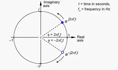
The imaginary parts have the same magnitude, but opposite signs, so when you add both vectors the imaginary parts cancel each other, leaving a purely real signal.
If counterclockwise rotation stands for positive frequency, clockwise rotation has to stand for negative frequency.
stevenvh
- 145,145
- 21
- 455
- 667
-
4I was never a fan of the graphical phasor approach but to each his own. You've got your clockwise / counter-clockwise backwards though, counter-clockwise is 'positive frequency'. – Mark Jun 17 '11 at 06:43
-
-
As soon as you have an observer, you've established a frame of reference, from which comes the potential for negative relative measurements. – Eryk Sun Jun 17 '11 at 12:52
-
Modulate a unit amplitude, 1 Hz sinusoid by 100 Hz, and you'll see the negative and positive frequency components shifted to 99 Hz and 101 Hz, each with 50% of the power. The full 1 Hz signal is now in the envelope of their sum. Baseband is where the two coincide, since cos(0 - x) = cos(0 + x) and -sin(0 - x) = sin(0 + x). – Eryk Sun Jun 17 '11 at 12:54
-
-
@stevenvh How do you guys get these fancy pictures in your answers? – NickHalden Jun 17 '11 at 15:55
-
@JGord the equations are just LaTeX which is built into this stack exchange: http://meta.electronics.stackexchange.com/questions/434/test-the-new-latex-markdown-in-this-sandbox-question The images are just images, you can upload from your computer or link to a URL when answering, this feature may require a certain amount of reputation to use. – Mark Jun 17 '11 at 17:46
-
@JGord, It's [markdown formatting](http://daringfireball.net/projects/markdown/syntax#img): ``. Omit the exclamation mark if you only want a link. The answer editor also has an image tool that will upload an image from your computer to imgur.com and insert it using reference-style markdown. – Eryk Sun Jun 17 '11 at 17:49
-
-
@eryksun sorry I don't understand what you mean by the negative and positive components shifted to 99 and 101 with 50% power. It looks to me just like a 100 Hz wave but superimposed (multiplied with?) onto the 1 Hz wave. Could you explain that comment for someone whos intro signals class was terrible? Thanks – NickHalden Jun 21 '11 at 18:34
-
1@JGord, product-to-sum: `cos(x) * cos(y) = 0.5 * cos(x - y) + 0.5 * cos(x + y)`. I plotted `0.5 * cos(99*t) + 0.5 * cos(101*t)`. WRT to signal processing, the spectrum of a 1 Hz cosine is two delta functions at +/- 1 Hz with weight 0.5. Multiplication in time is convolution in frequency, and convolving with a delta is a shift. When modulated by a 100 Hz carrier, the deltas at +/- 1 Hz shift to 99, 101 Hz and -99, -101 Hz, each with magnitude 0.25. That's 4 complex exponentials, or 2 cosines. – Eryk Sun Jun 21 '11 at 20:10
-
1@JGord your correct, it is just two waves multiplied together which can be explained completely in the time(real) domain. Where negative frequency comes in is that if you model that multiplication using a complex domain representation of those signals, you can think of it as just shifting the complex representation of the 1Hz wave up in frequency maintaining its positive and negative frequency components. Once your comfortable thinking about it in the complex domain this is a much simpler calculation than doing it in the time domain as the math the @eryksun provided shows. – Mark Jun 21 '11 at 21:59
-
2@JGord - while superimposed and multiplied (AM modulated) look similar you can easily tell them apart when looking at the positive and negative envelope. When superimposed the envelopes are in phase, when multiplied the negative envelope is a mirror image of the positive. – stevenvh Jun 22 '11 at 05:48
-
1@JGord - Sorry, I forgot the factor of `2*pi`. I plotted `0.5 * cos(2*pi*99*t) + 0.5 * cos(2*pi*101*t)`. The 1 Hz envelope emerges from the sum of the shifted positive and negative frequency components (-1 + 100 and 1 + 100). – Eryk Sun Jun 22 '11 at 09:03
-
17
It can't in reality.
A full answer would take an entire text book but the basic answer is:
In signal processing signals are often discussed as a sum of complex sinusoids (\$e^{j\omega t}\$) because its mathematically convenient.
This leads to Euler's formula:
\$e^{j\omega t} = cos(wt) + j \cdot sin(\omega t)\$
Which leads to its inverse:
\$cos(\omega t) = \frac{1}{2} \cdot (e^{j\omega t} + e^{-j\omega t})\$
Which implies that both positive and negative frequency is present which is where it pops up in signal processing discussion.
Mark
- 11,627
- 1
- 31
- 38
-
1But it should be clearly stated that "negative frequencies" do not exist in reality. However, its introduction simplifies many mathematic manipulations. – LvW Jul 22 '15 at 15:01
-
I rolled back the last edit. My point here is that negative frequency doesn't existing in 'reality', as in the 'real physical world', nothing to do with 'real valued' sinusoids. – Mark May 09 '16 at 13:51
8
The way I see it:
This is a complex sinusoid (\$e^{i\omega t}\$):
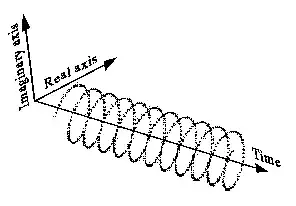
It can also be drawn less intuitively like this (left side), and has a one-sided spectrum like this (right side):

Negative frequency just means the helix is rotating the opposite way, and the spectrum is a delta function on the negative side of the frequency axis instead.
If you add a complex sinusoid of positive frequency with one of the same but negative frequency, the counter-rotating imaginary parts cancel out and it produces a real sine wave.

In this case, it's meaningless to talk about a sine wave with negative frequency, since a sine wave contains both positive and negative frequencies.
(I'd really like to make better illustrations of this, instead of copying these old poor-quality ones, but I've tried and it isn't easy. I think the 3D diagram of the spectra above is actually wrong. The delta functions should be parallel to the real/imaginary plane, and perpendicular to the frequency axis.)
endolith
- 28,494
- 23
- 117
- 181
-
-
@stevenvh: I rephrased it on DSP.se: http://dsp.stackexchange.com/a/449/29 – endolith May 22 '12 at 21:12