3

I have been looking over various data sheets for hours and still am not sure how to select an apporiate device. I am looking to send 5V 10mA pulses at 100-300kHz (to be determined) to a motor driver from my beaglebone 3.3V outputs. My plan is to use an N-channel MOSFET in this configuration:

http://www.americanmotiontech.com/Upload/DriveConnection/M542-05.gif 
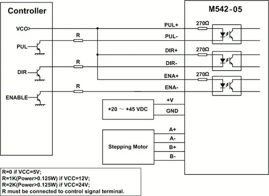
Where Vcc will be connected to the 5V line from Beaglebone and the gates connected to the GPIOs with internal pull-downs enabled.

I have this particular MOSFETs in mind but am not sure if it will work. http://www.diodes.com/datasheets/ZVN3320F.pdf

I am still not sure what parameters I have to be looking for in these data-sheets.

Should I be looking for minimum Vgs, and what effect does this even have on the circuit?

DiBosco
  • 1,384
  • 9
  • 19
  • 3
    You say you want to "use an N-channel mosfet", but your schematic doesn't include any n-channel MOSFETs. – The Photon Feb 15 '15 at 17:51
  • 1
    What you want is a *level translator*. You should probably only use an optocoupler if you also need galvanic isolation or need to break a ground loop---otherwise you're taking on extra cost and performance limitations for no reason. – The Photon Feb 15 '15 at 17:57
  • That schematic is from the motor driver manual. The opto couplers are inside the drivers. Is there any problem with putting N channel mosfets where the transistors shown are, with the drain'sto the (-) of the the driver'sm source's to ground and gate's to my beagleboen GPIO's for toggling. –  Feb 15 '15 at 18:06
  • That should work, but it's likely easier to find a BJT than a MOSFET to drive the opto with 3.3 V input. Note your FET datasheet defines threshold voltage with Vds = Vgs. That means the FET drain will possibly still be at 3 V when you have it switched "on". Or it could be substantially lower. Which might make it hard to choose a current-limit resistor for the opto input. – The Photon Feb 15 '15 at 18:35
  • Possible duplicate of [3.3v to 5v conversion with non-5v tolerant part. (single npn transistor?)](https://electronics.stackexchange.com/questions/258561/3-3v-to-5v-conversion-with-non-5v-tolerant-part-single-npn-transistor) – Dmitry Grigoryev Oct 24 '18 at 08:11

3 Answers3

0

Depending on the transfer ratio of the optocouplers inside the stepper driver you could attach VCC to 3.3V and drive the LEDs directly from your beaglebones ports. They can source/sink ~4mA. I believe you will be even more limited by Rled.

If you're not willing to give a try or if you have long cables then you can use a single buffer/line driver(such as 74**451) instead of multiple discrete FETs or level shifters.

Wesley Lee
  • 7,844
  • 6
  • 35
  • 53
  • I have no idea about the transfer rate, but the driver manual says logic HIGH is 4-5V, 7mA minumum with 1.5us or greater pulse width. My goal is to actually control three of motors. I hooked one up in the configuration posted above with a 2n3904 and the VDD 5v begalebone pin supplying the Vcc, I was only able to get the motor spinning with a pulse width of 150us or greater (using the PRU's). I don't have a scope so I am not sure what the waveform actually looked like. These line buffers look pretty simple to use, are they more desirable for my application? –  Feb 16 '15 at 08:50
  • The line drivers will probably be easier to assemble if you are going to use multiple channels. Also, depending on how you are programming your BBB, I'm not sure you can reach 100kHz~300kHz . See: http://chiragnagpal.com/examples.html At first he got 3k5~Hz, then later 2.8MHz. – Wesley Lee Feb 16 '15 at 09:04
  • I am writing directly to the hardware registers using PRU assembly where each instruction is 5ns. I tested the code with visible pulse widths and everything was ok, so ensuring the GPIO toggling frequency is just a matter of changing a #define directive. I am having some difficulty finding the specific buffer you suggested, could you toss me a link? –  Feb 16 '15 at 09:26
  • I filtered them (PTH parts, less than 3V minimum supply voltage.. if you want different ones just reset the filters) http://br.mouser.com/Semiconductors/Logic-ICs/Buffers-Line-Drivers/_/N-50nah?P=1z0z63xZ1yzmm17Z1yzmm1aZ1yzmm1c&Keyword=74+541&FS=True – Wesley Lee Feb 17 '15 at 05:46
  • Thanks, I actually found these http://www.ti.com/lit/ds/symlink/sn74ahct1g125.pdf which are just the single versions pretty much. I am a little confused though if I need current limiting resistors or if there are internal ones? I need a 10mA output current, so would it be okay to just put a 470ohm resistor between the 5v supply and Vcc pin? Also, can I just tie the Output enable pin to ground if I am just using this as a one way level shifter, 3.3 volt input, 5v output? –  Feb 17 '15 at 13:22
  • The operating range for this IC is 4.5~5.5V, so I think its not advisable to use it on the BB. If you are contemplating using single devices then I would just go with FETs. This device is common and suitable: https://www.fairchildsemi.com/datasheets/2N/2N7000.pdf It tolerates 60V and 200mA and turns on at 2~3V. The calculation for the optocoupler resistor is: 5V-Vled = R*0.007ma(minimum). Supposing Vled ~= 1.5, then R = 500. For 270R resistor then they are going for about double that current. Im quite sure they have internal resistors but you could add one yourself for safety. – Wesley Lee Feb 18 '15 at 01:48
0

I am using a circuit for RPI as follows: enter image description here

But this is not very fast(Not required in this case).

Note: Personally I dont have any Optocoupler that can handle 300Khz signal, still this might help you.

0

Too messy - just use a 74ac125 as a buffer to the opto's, power with 5V.

https://www.digikey.com/product-detail/en/on-semiconductor/MC74AC125DG/MC74AC125DGOS-ND/1479360

CrossRoads
  • 3,453
  • 1
  • 6
  • 14