2

I can understand some of the electronics concepts and components, like diodes, resistors, thyristors, capacitors, inductors. But transistors I still fail to grasp the way they work and what role they play when in a circuit.

  1. Can I understand them only reading theory about them, without hands-on lab experiences?

  2. What good literature (preferably on the Internet) can you recommend to me about transistors, for a person that understood a broad area of other components, but transistors still are a big enigma?

  3. Is there some free online simulator where I can place circuits including transistors and after see the electrons fluxing,immitating a real-life circuit?

sergiol
  • 381
  • 4
  • 21
  • 2
    How did you understand thyristors without understanding transistors? – Ignacio Vazquez-Abrams Feb 14 '15 at 23:23
  • I understand a thyristor as a diode which can pass current between Anode and Cathode only after the Gate has received the control current; and after that if we stop to feed the control current to the Gate it continues to drive current between Anode and Cathode. Is my understanding too basic or untrue? – sergiol Feb 14 '15 at 23:33
  • No, I was just using the wrong definition of "understanding". – Ignacio Vazquez-Abrams Feb 14 '15 at 23:35
  • 1
    http://www.falstad.com/circuit/ This is a java applet that shows the electron flow like you asked. It is completely free and I absolutely love it for understanding what is happening in a circuit. Under Circuits->Transistors->NPN Transistor, you will see an example of a transistor working. – Addison Feb 15 '15 at 00:03
  • @sergiol, your description of a thyristor's function is also an approximate description of an "NPN" BJT/FET. It is not quite either, because FET's turn ON or OFF, but are voltage-controlled, while BJT's are current-controlled, and can be turned "partially" on. – Jon Feb 15 '15 at 00:04
  • @Jon: If that's true, what parts of the NPN BJT and NMOS FET correspond to the A, K and G of the thyristor? – sergiol Feb 15 '15 at 00:19
  • 1
    A G K "=" (NPN BJT) C B E "=" (NFET) D G S – Jon Feb 15 '15 at 00:28
  • For either polarity, a BJT's gate always flows to/from the emitter. For either polarity, a FET's gate voltage is relative to source. – Jon Feb 15 '15 at 00:38
  • Thanks, Jon. I think some part of my not so good understanding of the transistor is related to trying to understand it using the Conventional sense of current. It is much easier to understand approaching it by the Real sense. If we call the legs of the transistor "Electrons' emitter", "Electrons' collector", and "Control Terminal" things seems to be really easier to understand. – sergiol Feb 15 '15 at 01:05
  • You should be able to use any FET with just the first diagram I made. The second diagram shows how biasing can affect the output. After you are familiar with the polarities, biasing will be its' own animal. – Jon Feb 15 '15 at 01:25

7 Answers7

6

Since you have a good grasp on the other components, transistors should be no problem at all to understand. Doing a quick search around here, I found a post that I think sums it up very well.

Basics of Transistors

Think of a NPN transistor this way: You put a little current thru B-E, and that allows a lot of current thru C-E. The ratio of a lot to a little is the transistor gain, sometimes known as beta and sometimes hFE.

To sum it up, a common use of transistors is as an amplifier, or even simpler, a switch. A good example would be powering a motor by using a microcontroller for a robot. You want to be able to turn the motors on/off, which is what the microcontroller will do. If you were to hook the motor straight up to a MCU digital pin, you would destroy the MCU because it cannot handle the currents typically needed. Instead, you use a transistor that will use a small amount of current through the B-E but will allow larger currents to flow through C-E.

Addison
  • 652
  • 5
  • 15
  • Thanks. I added a 3rd point to my question hoping someone answers it. – sergiol Feb 14 '15 at 23:51
  • @sergiol For an answer to your third question, you can try EveryCircuit: http://everycircuit.com/. It is a circuit simulator that animates the current. There is an online version and an app version. I have the app version: I highly recommend it even though it was $9.99 (I don't know what it is now). – FullmetalEngineer Feb 14 '15 at 23:59
  • @pikafu: Thanks. I just noticed my Android phone has an application I had installed sometime ago, called Droid Tesla, the unpaid version. But it doesn't have animated electron flux and much of components are only available on the paid version. – sergiol Feb 15 '15 at 01:19
3

A transistor is [sort of] a variable resistor. At it's most extreme, it's either a total short or infinite impedance [ie. an open or closed switch].

Put a transistor in series with a standard resistor. Depending on how you set up the transistor, the resistor is bigger OR smaller. Going by resistor theory, the voltage across each device also changes. When the signal controlling the transistor is small, but the voltage swing across the resistor is bigger, you have: an amplifier.

Electron flow? Easiest to understand is a standard depletion mode JFET. Think of the source to drain as a conductive tube. When you apply a [reverse bias] voltage to the gate, you create a non-conducting zone - and the tube gets thinner. Thinner tubes have higher resistance, and if you bias the gate hard enough it's like pinching off a garden hose.

BJT's remind of a scene from King Kong. The heroes get chased by dinosaurs, they duck around a corner - but the dinosaurs can't all stop in time and fall over a cliff. The small ledge the heroes use is the base, and the heroes are the base current. The large alley leading up to the edge is the emitter. Dinos plus heroes = emitter current. Dinos falling over the cliff edge, out of control = collector current.

Hands-on experiments help, but a basic idea is key to understanding. It doesn't need to be totally accurate, just memorable enough. I believe educators call this sort of stuff "visual aid learning".

Alan Campbell
  • 1,019
  • 6
  • 10
  • AlanCampbell, with all respect, I am afraid your "intuitive explanation" is a bit too simple (to avoid the word "false"). The questioner wants to UNDERSTAND the working principle of BJT`s. "A sort of variable resistor"? Does a change of the voltage across this "resistor" influence the current? No! Why not telling him the truth: A voltage controlled (non-ideal) current source? – LvW Mar 01 '15 at 09:44
  • @LvW the school I went to had many different transistor models. Each one was a little more accurate than the previous versions. Does that make the simpler versions "wrong"? Is the understanding that comes from the simpler models invalid? You are, of course, free to publish a version that is more accurate than mine. Balancing accuracy and understanding can be a tricky act. – Alan Campbell Mar 02 '15 at 09:33
  • I know several different "models" (Ebers-Moll, Boyle, Gummel-Poon,..) - however, a model consisting of a "variable resistor" is - in my view - simply wrong. A model should be able to exhibit at least the most important properties and dependencies. As I have mentioned, the current through the C-E path is (nearly) independent on the corresponding voltage VCE. I think, this does not correspond with a resistive behaviour. – LvW Mar 02 '15 at 10:16
  • @LvW I look forward to reading your version of an answer to the OP. – Alan Campbell Mar 02 '15 at 12:59
  • @A.Campbell,as an answer I did mention two documents (links). More than that, for my opinion, the answer from JTT did cover a lot ("BJTs have an exponential relationship.") More than that, the main question (is the BJT current or voltage controlled) was discussed in the past very often - also in this forum. (And my experience: For some people, the answer to this question is a kind of "religion" - just a belief without justification.) – LvW Mar 02 '15 at 13:16
  • To continue: ... and that is the reason I didn`t want to start the "religious" discussion again (I think, you will be not surprised that I do not follow your analogy with "heroes" and "King Kong"?). – LvW Mar 02 '15 at 13:23
  • @LvW I liked the answer from JTT as well. So I upvoted it. Please consider doing the same: this conversation has become counter-productive. – Alan Campbell Mar 04 '15 at 00:59
2
  1. It depends on your learning style. I think you need both textbook and lab experience to truly grasp the concepts. Are there any hacker spaces near you?

  2. There are countless explanations about transistors around. They're all written with different audiences in mind. Some focus on the underlying physics, some focus on the applications, others focus on intuition. You'll have to keep reading (and working problems, and building circuits) until you find one that vibes with you.

  3. As others have pointed out, there's CircuitLab. If you have an iOS device, you can try iCircuit, which does animate the current flow. Then there are the countless SPICE distributions. I personally like Multisim. Mouser makes a free version available.

To put in my two cents about transistors: a transistor is what you make of it.

You can think of it as a black box. That is, it's a three terminal device that defines some relationship between the voltages and currents. Ideally, if you apply a voltage between two terminals, then the current through the third terminal is completely determined.

The specific nature of this relationship depends on the type of transistor you're using. FETs have a square law relationship: the output current is proportional to the square of the input voltage. BJTs have an exponential relationship. Vacuum tubes have a 3/2 power law.

With this magic black box, you can build lots of useful things. The two most popular applications are amplifiers and switches. For a voltage amplifier, the goal is to have a small wiggle in voltage at some terminal generate a bigger wiggle at another terminal. If we apply this small voltage to our controlling transistor terminal, then we get an output current that that scales exponentially or quadratically, and then we can convert this to a voltage. As a switch, if you apply zero voltage between the controlling terminals, then the output current goes to zero. The device shuts off.

This is a gross oversimplification, but I think that captures the main idea. The devil is in the details. Real transistors have lots of requirements to keep them operating in a desirable way. It'd be great if such a magic ideal transistor existed- we'd have incredibly spec'd electronics with amazing battery life! However, device engineers and physicists can only give us devices that roughly approximate this ideal transistor.

For FETs, there's a threshold voltage that must be met before the device will turn on. There's also a fourth terminal (body) that can influence device behavior. If the output voltage is below a certain level, it behaves more like a resistor. Beyond a certain level, it acts like a current source. Oh, and that output current has a slight variation based on that output voltage. And if you're talking about short channel FETs, that square law relationship isn't really true anymore. For BJTs, that input voltage also has to supply some current as well (You will doubtless run across arguments over whether a BJT is voltage or current controlled. It is both; you can't have one without the other.). Then there are parasitic capacitances that affect the transistor operation at high frequency. And on and on and on.

There is always more to learn. I am still learning. Hope this helps.
qce88
  • 126
  • 2
1

A transistor is built from two antiparallel diodes. A diode will admit current in one direction and block it in the other. The way it blocks this is by having a load depletion zone without charge carriers. This happens when you suck off electrons at the N-doted part (which conducts using extra electrons) of the diode and holes at the P-doted part (which conducts using missing electrons) of the diode. That's pretty easy to understand so far.

When a diode conducts, it works by recombining electrons and holes at the boundary of the N and P doted parts.

Now the trick with a transistor is that the bulk of electrons (for an NPN transistor) flowing from the emitter into the base don't recombine with holes in the base but pass through into the collector (which is operated in blocking direction). As a result, the current from emitter to collector is much greater than the "governing" current from emitter to base.

By working with the material parameters such that the average "recombination length" in the basis is a sizable multiple of the actual base thickness, one can have a somewhat predictable influence on the respective amplification factors.

Actual circuit design stabilizes the operating conditions of the transistor by providing bias and negative feedback and results in more stable and linear (though smaller) amplification than the naked transistor would provide.

user66805
  • 11
  • 1
0

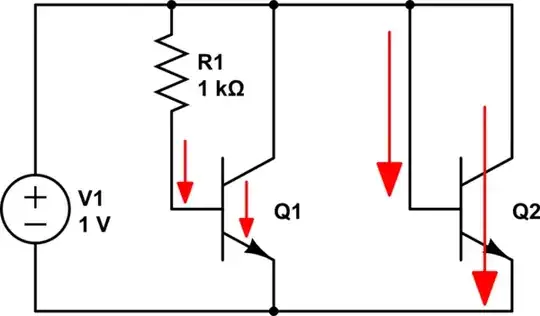
Supplemental to my comment: (+1 for graphic!)

(All other components omitted)

schematic

simulate this circuit – Schematic created using CircuitLab

Notice that if the arrows both point toward or away from the device, it is off. BJT's work the same way, but can be turned "partially on" in proportion to the gate current, rather than just ON or OFF.

NPN BJTs:

schematic

simulate this circuit

Notice that the size of the arrow across the transistor and the one at the gate are proportional. Also, notice that Q2, in this configuration, "is a diode".

Jon
  • 742
  • 3
  • 12
  • what means "partially on"? – sergiol Feb 15 '15 at 01:08
  • by "partially on" you mean to use a resistor to pass only some current, right? (is that what you mean by "biasing" on your comment?) – sergiol Feb 15 '15 at 01:39
  • When a FET's gate reaches threshhold, its resistance "instantly" drops to a particular value, RDS(on), typically measured in mOhms. The bias resistor on BJT Q1 limits gate-emitter current, so collector-emitter current is also limited. With no resistor, like Q2, a BJT can also turn "all the way" ON or OFF. – Jon Feb 15 '15 at 01:40
  • Correct. Just for discussion, if Q1 gate-emitter current is limited to 1mA, the source-emitter current will be limited to 10mA; that's a gain of 10x. With Q2, the gate conducts as much as it can, so the emitter does too. Biasing becomes important when source-emitter current interferes with gate-emitter current; i.e. if the transistor turns on all the way, will gate still be able to drain? That's why NPN's are more-frequently used as switches on the "down-stream side" (GND); they can almost always drain properly when emitter is directly grounded. – Jon Feb 15 '15 at 01:45
0

What good literature (preferably on the Internet) can you recommend to me about transistors

Here are two links I can recommend ( because the BJT is correctly described as a voltage controlled current source):

http://www.eecs.berkeley.edu/~hu/Chenming-Hu_ch8.pdf

http://www.google.de/url?sa=t&rct=j&q=&esrc=s&source=web&cd=2&cad=rja&uact=8&ved=0CCkQFjAB&url=http%3A%2F%2Fwww.simonfoucher.com%2FMcGill%2FECSE330%2520Electronics%2FNotes%2F5.1%2520BJT%2520Part%25201.pdf&ei=nnLgVP_NIcK9UaaggfAI&usg=AFQjCNFXBYfvKuP83e1zVHx3kP8EncfooQ&bvm=bv.85970519,d.d24

LvW
  • 24,857
  • 2
  • 23
  • 52
0

Yes, you can easily learn about transistors with out hands on experience

The best online source for all things concerning the fundamentals of electrical engineering is, in my opinion, still the following link.

http://www.phy.davidson.edu/instrumentation/NEETS.htm

For your purposes, you want to download the PDF for module 7, as it covers the basics of how transistors operate. The PDF is about 300 pages, but you will be interested in the first 75 or so pages as this portion covers the core solid state knowledge you need to get a basic understanding of transistors.

dataBus
  • 66
  • 3